
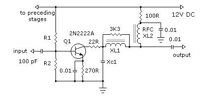
Signal Tracer

This circuit is designed to generate narrow pulses within the frequency range of 700-800 Hz, making it suitable for various testing applications in audio and radio-frequency domains. The output pulses are rich in harmonics, extending into the MHz range, which allows for effective testing of amplifiers and receivers by injecting these pulses into their respective stages.
The circuit's operation begins with the generation of narrow pulses, which can be achieved using a 555 timer IC configured in astable mode. This configuration allows the timer to continuously oscillate, producing the desired frequency. The output of the timer can be coupled to a transistor stage to amplify the pulses further, ensuring that they can effectively drive the input of the audio or RF stages of the device under test.
To utilize this circuit for testing, a clip is connected to the ground of the device under test. The probe is then used to touch various stages of the circuit, starting from the last stage and moving towards the first. This methodical approach allows for the identification of faulty stages; if the high-pitched tone generated by the circuit is no longer audible, it indicates that the preceding stage is defective.
Additionally, the circuit includes a feature that allows for the connection of an earclip or headphones to the output jack (J1). When connected, the circuit transitions into a two-stage amplifier configuration. This modification enables the circuit to capture any audio signals from the device under test, which can be amplified and heard through the headphones. This capability enhances the utility of the circuit, allowing for both pulse generation and audio signal amplification in a single testing setup.
Overall, this circuit serves as an effective tool for diagnosing faults in audio and RF circuits by providing both a clear indication of operational integrity and the ability to listen to audio signals directly from the device under test.This simple circuit generates narrow pulses at about 700-800Hz frequency. The pulses, containing harmonics up to the MHz region, can be injected into audio or radio-frequency stages of amplifiers, receivers and the like for testing purposes. A high-pitched tone can be heard from the speaker of the device under test when all is working properly.
The clip must be connected to the ground of the device under test, touching with the probe the different stages of the circuit, starting from the last stage and going up towards the first. When the tone is no longer heard, the defective stage has been found. Connecting an earclip or headphone to J1, the circuit will automatically change into a two-stage amplifier and any audio signal coming from the device under test and picked-up by the probe will be heard through the headphones. The testing of a circuit sho 🔗 External reference
Related Circuits
A small signal amplifier, perhaps of the type to follow the previous buffer amplifier. We will assume we are buffering and amplifying our signal from the voltage controlled oscillator tutorial. In those examples we were generating and buffering 1.8...
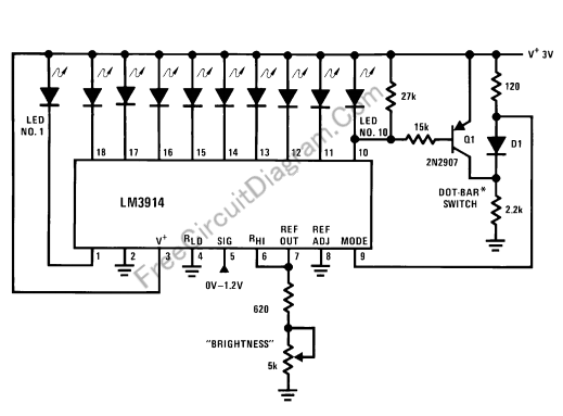
This LED (Light Emitting Diode) display consists of 10 LEDs to indicate the level of an input signal. If the signal is low, only LED #1 will light up. As the signal level increases, the illuminated dot will progress...
Suitable for matching diodes or examining the VI characteristics of two-terminal devices (such as diodes), this circuit is designed for laboratory use. Resistors R1 and R2 can be increased in value, and a higher voltage transformer can be utilized...
The circuit depicted in the figure is a generator that includes an oscillator, a voltage follower, a zero amplitude adjustment, and a zero shift circuit. It is utilized as a self-balancing recorder for testing signals. The output signal ranges...
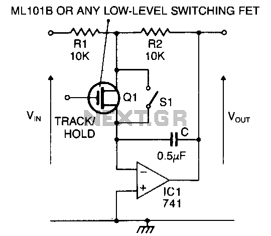
When the switch is closed or the FET is conducting, the circuit functions as an inverting amplifier with a gain of R2/Rl. The inverting terminal of the op-amp acts as a virtual ground, allowing the capacitor to remain charged...
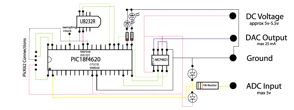
The circuit below demonstrates how to construct a DAQ_LITE device, accompanied by an image of the finished PCB board. It is important to note that the 80mA fuse depicted in the image and the nearby protection diode are recommended...