
Simple Diode Curve Tracer

The circuit in question serves as a versatile tool for analyzing the voltage-current (VI) characteristics of two-terminal devices, primarily diodes. The fundamental operation involves applying a varying voltage across the device under test, allowing for the observation of current flow and the corresponding voltage drop. This is essential for understanding the behavior of diodes under different conditions, including forward and reverse bias.
To implement this circuit, a transformer is typically employed to step up the input voltage to the desired level. The transformer must be selected based on the maximum voltage requirements of the devices being tested. Additionally, the resistors R1 and R2 play a critical role in setting the current limits and ensuring safe operation. By increasing the values of these resistors, the circuit can accommodate devices with higher current ratings without risking damage to the components or the device under test.
The circuit can be further enhanced by incorporating measurement devices such as ammeters and voltmeters, which can provide real-time readings of current and voltage, respectively. This allows for precise plotting of the VI characteristics on a graph, facilitating a deeper analysis of the diode's performance.
Furthermore, additional features such as variable resistors or potentiometers can be integrated into the circuit to allow for fine-tuning of the test conditions. This adaptability makes the circuit suitable for a wide range of laboratory applications, from educational demonstrations to advanced research in semiconductor behavior.
In summary, this circuit is an essential tool for electronics laboratories, providing a reliable method for evaluating the characteristics of diodes and similar two-terminal devices through adjustable voltage and current settings. Suitable for matching diodes or examining VII characteristics of two terminal devices (diodes, etc.), this circui t should be handy for lab use. Ri and R2 can be increased in value and a higher voltage transformer can be used for higher voltage test using this principle.
Related Circuits

This circuit can be used to drive a 12V relay with a triggering signal of 5V. It incorporates two 1N4002 diodes, one 2N3904 transistor, and two resistors. By altering the resistor values, the input triggering voltage can be modified. The...
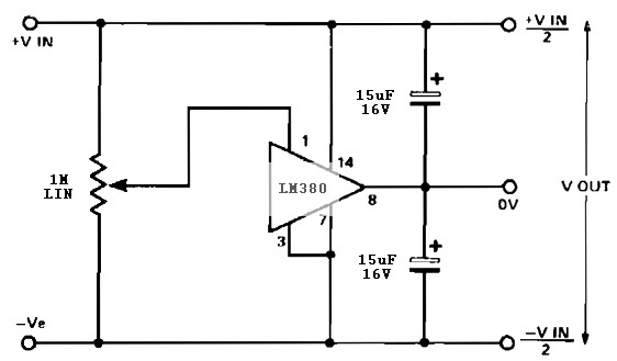
A simple split rail power supply based on the LM380 power supply. The design is intended to provide an inexpensive high-power supply, initially available in three power levels. A wide range of accessories is included to maintain an attractive...

The tracer detects the weak magnetic field of any current-carrying house wiring and amplifies this signal to a level that is adequate for driving a magnetic earpiece. The unit uses a telephone pick-up coil to detect the magnetic field. The...

This is a simple high-frequency signal generator. By changing the inductance of the LC resonant circuit using the band switch S1, the high-frequency oscillation frequency range can be altered. The generator is divided into four frequency stages: the first...
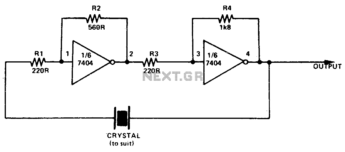
This simple and inexpensive crystal oscillator consists of one-third of a 7404 IC, four resistors, and a crystal. The inverters are biased into their linear regions by resistors R1 to R4, while the crystal provides the necessary feedback. Oscillation...
This 555 timer based PWM controller features almost 0..100% pulse width regulation using R1, while keeping the oscillator frequency relatively stable. The frequency is dependent on values of R1 and C1, values shown will give a frequency range from...