
Simple 12V battery circuit with diagram

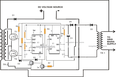
The 12V battery charging circuit is designed to charge lead-acid batteries using a trickle charging method, ensuring a safe and efficient charging process. The circuit typically includes a transformer, a rectifier, a filter capacitor, and a voltage regulator to maintain the appropriate charging voltage.
The transformer steps down the AC voltage from the mains supply to a lower AC voltage suitable for charging the battery. The rectifier, often composed of diodes, converts the AC voltage to pulsating DC voltage. A common configuration is a full-wave rectifier, which utilizes four diodes arranged in a bridge configuration to improve efficiency.
After rectification, the pulsating DC voltage is smoothed using a filter capacitor, which reduces voltage ripple and provides a more stable DC output. This output is then fed into a voltage regulator, which ensures that the voltage remains at a safe level for charging the lead-acid battery, typically around 13.8V to 14.4V, depending on the specific battery chemistry and state of charge.
Additional components may include a current-limiting resistor or a charge controller to prevent overcharging, which can lead to battery damage. The trickle charger operates by supplying a low and constant charging current, which is ideal for maintaining battery health over extended periods without causing overheating or excessive gassing.
This circuit can be implemented using discrete components or integrated circuits designed for battery management. Proper heat dissipation methods, such as heat sinks for the rectifier diodes, should be considered to ensure reliable operation during charging. Overall, this 12V battery charging circuit is an effective solution for maintaining lead-acid batteries in various applications.A 12V battery full charging circuit with simple diagram for rectifier is given.The lead acid trickle charger circuit is explained with a rectifier.. 🔗 External reference
Related Circuits
This document outlines a simple PWM (Pulse Width Modulation) DC to AC voltage inverter circuit based on the SG3524 integrated circuit. The SG3524 is a fixed frequency PWM voltage regulator control circuit that offers indifferent outputs suitable for both...
A single IC 556 has been utilized to generate PWM pulses. One half of the IC is configured as a high-frequency generator, which supplies the other half of the IC, set up as a pulse width modulator. The modulating...
This circuit is designed to operate an electric strike or an electromagnetic lock on a door. It does not control the door's opening or closing but rather activates a small electromagnetic strike that unlocks the door. The opener features...
A step-down transformer converts AC 220V to a lower voltage. A diode bridge rectifier and filter capacitor provide a direct current (DC) output, which fluctuates with variations in the grid voltage. A resistive voltage divider is used for sampling....
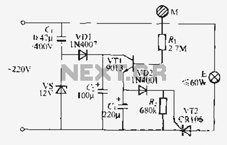
Utilize the call sheet to touch the electrical threshold M, which causes the E lamp to light up. When the same interval subparagraph is triggered, the lights will automatically turn off. A voltage regulator rectifier circuit is formed using...
This circuit activates an alarm whenever an object crosses the laser beam emitted by a laser. The output of the IC TL071 goes high when the laser beam is interrupted. This output voltage is further amplified by an NPN...