
Lie detector circuit

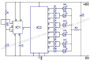
The lie detector circuit utilizes the principle of galvanic skin response (GSR), which measures the electrical resistance of the skin to determine psychological states. The circuit typically consists of a power supply, resistors, an operational amplifier, and a microcontroller or analog output to interpret the resistance values.
The resistance of human skin varies significantly based on moisture levels, emotional states, and other physiological factors. In a standard setup, electrodes are placed on the skin surface, usually on the fingers or palm. When a person is calm, the skin resistance is high, approximately 1 Megaohm for dry skin. However, during moments of stress or deception, the skin tends to become more conductive due to sweat gland activation, resulting in lower resistance readings.
The circuit is designed to convert the varying resistance into a measurable voltage signal. This is often achieved by using a voltage divider configuration where the skin resistance is one of the resistors in the divider. The output voltage, which correlates with the skin resistance, is then fed into an operational amplifier for amplification and further processing.
The microcontroller can be programmed to analyze the output signal and determine thresholds that indicate significant changes in skin resistance. These thresholds can be calibrated based on test subjects to enhance accuracy. The final output can be displayed on an LED indicator or sent to a computer for more detailed analysis.
In summary, the lie detector circuit is a practical application of electronic components to measure physiological responses, providing insight into human emotional states based on skin resistance variations.This is a false capture circuit or Lie detector circuit. The basic principle of the resistance of human skin. While dry skin is a resistance of about 1 Mega ohm.. 🔗 External reference
Related Circuits
The following circuit illustrates an LED Knight Rider Circuit Diagram. This circuit is based on the 4017 and 555 integrated circuits. Features include the Knight Rider effect with four LEDs. The LED Knight Rider circuit is designed to create a...

This is a simple circuit that features high-performance power amplifiers. The power amplifier is available as a PCB, along with a complete list of components. The described circuit utilizes high-performance power amplifiers, which are essential for applications requiring significant signal...

This design has not been referred to as a GOLD detector, as that term is reserved for more complex devices capable of distinguishing gold from other metals. There is a significant difference between detecting gold and ordinary metals, known...

In this circuit, an LM339 quad voltage comparator is utilized to generate a time delay and control a high current output at low voltage. Approximately 5 amps of current can be sourced using a pair of fresh alkaline D...

This NiCd battery charger circuit schematic can charge 6 volts as well as 12 volts NiCad batteries. It uses a transformer that can deliver 4 to 5 A current. The NiCd battery charger circuit is designed to accommodate both 6V...
The most significant omission was that the DRUID did not accept confirmation codes (i.e., the solution to the clue) and did not provide directions to the next clue site. Instead, teams had to call in and confirm with Game...