
Simple Audio Test Oscillator Circuit

The circuit employs an 88 mH toroidal coil, which serves as a crucial inductor in the oscillator design. This inductor is characterized by its compact form factor and efficient magnetic properties, making it suitable for high-frequency applications. The oscillator operates at a frequency of 1 kHz, a common frequency for various signal generation tasks, including audio applications and timing circuits.
The output voltage capability of up to 8 V peak-to-peak indicates that the oscillator can drive a high-impedance load effectively, which is essential for interfacing with other electronic components or systems that require a stable voltage level. The high-impedance load ensures minimal current draw, allowing for efficient operation of the oscillator circuit.
The total harmonic distortion (THD) of 0.9% suggests that the output waveform is relatively clean, with minimal distortion introduced by the oscillator. This level of THD is acceptable for many applications, where fidelity of the signal is important, such as in audio systems or precision timing applications.
For implementation, the oscillator circuit can be constructed using additional components such as capacitors for tuning, transistors or operational amplifiers for signal amplification, and resistors for biasing. The toroidal coil's inductance plays a vital role in determining the oscillation frequency alongside the capacitive elements in the circuit. Proper layout and component selection are crucial to minimize parasitic effects and maintain the desired performance characteristics. An 88-mH surplus telephone toroidal coil is used in a 1-kHz oscillator. Up to 8 V p-p into a high-Z load is available. THD is 0.9%.
Related Circuits

The R-C twin-tee passive circuit provides band-reject (notch) filtering suitable for portable applications. It has a loaded circuit Q of 0.25. Effective rejection is achievable when the bridge is balanced, which requires close tolerances of the adjustable components, and...
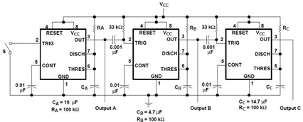
A sequential timer circuit device is utilized in various applications for initializing conditions during start-up or for activating test signals in sequences, such as in test equipment devices. The circuit diagram below illustrates a sequencer circuit with potential applications...
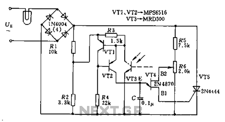
The circuit utilizes a thyristor-based AC automatic voltage regulator to stabilize the brightness of lamp L. A diagonal line connects the thyristor to the T5 bridge. The trigger pulse for the thyristor is generated by a single-junction transistor, VT4....
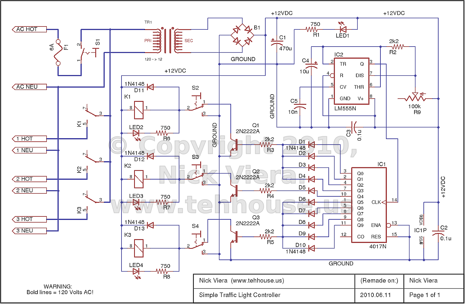
The controller is entirely hardware-based and provides the typical sequencing for a standard three-light traffic signal. This traffic light controller/sequencer was constructed during the initial learning phase of electronics. Although it may be considered crude and unattractive, it effectively...
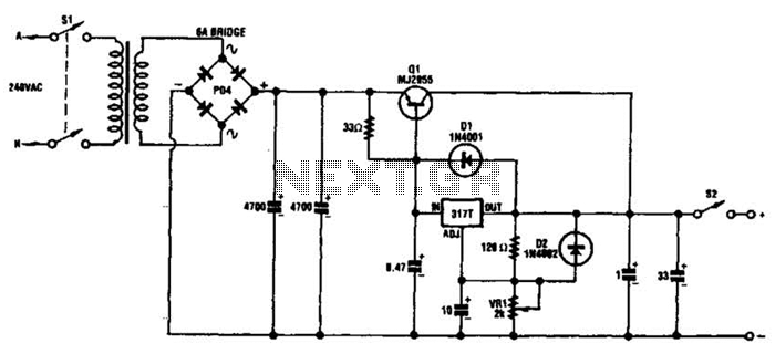
This circuit can deliver 3 A or more with a maximum DC voltage of slightly over 20 V. It is designed around the widely available LM317T adjustable 3-terminal regulator and incorporates a PNP power transistor to enhance the current...
The clock is based on the PIC16F877 microcontroller from Microchip Technology Inc., which performs all of the logic necessary to decode the MSF signal and display the time on twelve 7-segment displays. The circuit design incorporates the PIC16F877 microcontroller, a...