
traffic simple
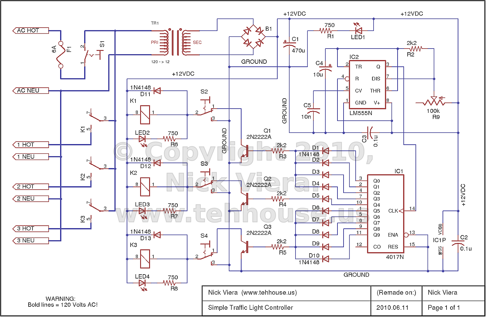
The basic operation of the traffic light controller is straightforward. A 555 Timer IC generates a voltage pulse at specific timing intervals, which are determined by a capacitor and two resistors, one of which is a potentiometer (a variable resistor). The 4017 decade counter IC has ten output ports, with only one port active at any time. Each pulse from the 555 Timer causes the 4017 to deactivate the current output port and activate the next one. Output port #10 is connected to the RESET pin of the counter, ensuring that when it attempts to activate output #10, it immediately resets to output port #1, allowing continuous looping from output port #1 through #9. Each output port corresponds to a different color of the traffic signal; for instance, output ports #1 to #4 control the red light, output port #5 controls the yellow light, and output ports #6 to #9 control the green light. This configuration means that the red and green lights are illuminated four times longer than the yellow light.
To prevent power from back-feeding into inactive ports on the counter, diodes are used to group the outputs for the red and green lights. Each of the decade counter's outputs is connected to a bipolar junction transistor (BJT) to amplify the signal, ensuring sufficient current to activate the coils of mechanical relays. The relays manage the AC mains power supplied to the traffic light lamps based on the signals received from the BJTs. This arrangement allows the relays to act as buffers, providing electrical isolation between the low-power control signals and the high-power 120-Volt AC used for the lamps.
It is important to note that the schematic closely reflects the actual design of the traffic light controller but has been modified for enhanced safety. Specifically, "override" switches for each output have been integrated into the low-voltage control signals for the relays rather than directly switching the 120-Volt AC, as was done in the original design. The bold lines in the schematic represent the 120-Volt AC wiring, which requires careful insulation and handling due to the potential lethality of line power. Caution is advised when working with this system.The controller is entirely hardware based, and provides the typical sequencing for a standard 3-light traffic signal. I built this traffic light controller / sequencer when I was firstlearning electronics, and it is what I would consider a crude and ugly device.
However, I learned a lot while building it, and it served its intended purpose. making the traffic signal I bought off eBay flash in the standard Green - Yellow - Red sequence. In addition, I built the controller with variable speed control, and the ability to "hold" any of the lamps full-on or full-off. The casing for the controller electronics is an old, re-used cookie tin. While not the most eloquent container; the cookie tin served its purpose while provided my circuit a unique and fire-resistant case.
If I were to rebuild this traffic light controller, I would suggest the use of a different casing material. The basic sequencing operation of this traffic light controller is simple. The 555 Timer IC generates a voltage "pulse" at a specific timing interval. This interval is set using a capacitor and two resistors, one of which is the potentiometer (basically a variable resistor).
The 4017 decade counter IC has 10 output ports, of which only one port is turned on at any given time. Each time the 555 Timer sends out a pulse, the 4017 decade counter turns off the currently-active output port, and turns on the next output port.
Output port #10 is connected to the RESET pin of the counter, so that anytime the counter tries to activate output #10 it ends up immediately jumping back to Output port #1 (i. e. it starts over counting from 1). In this way the counter loops continuously from output port #1 through #9. Each of the decade counter`s output ports is assigned to a different color light of the traffic signal.
For example, mine is connected so that output ports #1 to #4 control the red light, #5 controls the yellow light, and #6 to #9 control the green light. This means that the red and green lights are turned on four times as long as the yellow light is. The multiple outputs for the red and green lights are grouped together using diodes so that power doesn`t back-feed into ports on the counter which are currently off.
The collective red, yellow, and green outputs from the 4017 decade counter are each connected to a BJT. The BJTs essentially amplify the signal from the decade counter so that there is enough current to drive the coils of the mechanical relays.
Thus each BJT`s output is connected to its respective relay coil`s input. The relays turn on and off the AC mains power to the traffic light lamps based on the control signal they "see" from the BJTs. In this way they act as "buffers" between the low-power control signals and the high-power 120-Volts AC used to power the lamps in the traffic signal.
These mechanical relays also provide electrical isolation between the low and high-power systems in the controller. NOTE: This schematic very closely reflects the actual design of my simple traffic light controller, but has been modified to include several changes which increase the safety of this design.
Mainly, the "override" switches for each output are inserted into the low-voltage control signals for the relays instead of directly switching 120-Volts AC, as they did in the original design. The bold lines in the schematic represent the 120-Volt AC wiring. Extra care should be used to ensure this wiring is well-insulated. Remember, 120-Volt line power can be lethal. proceed with caution! 🔗 External reference
Related Circuits
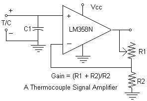
Continuing with the thermocouple interface concept, the next step is to amplify the TC's millivolt signal into a more readable analog voltage, on the order of 0 to 5VDC. This simple circuit fits the bill. The LM358N is a...
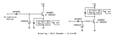
The two circuits illustrated show the operation of opening a relay contact shortly after the ignition or light switch is turned off. A capacitor is charged, and the relay remains closed until the voltage at the diode anode rises...
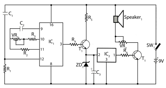
The circuit timer with a musical alarm utilizes a well-known CMOS oscillator/divider integrated circuit (IC1). Although this circuit operates at 9V, its standby current drain is minimal. The time delay of the timer circuit can be adjusted by modifying...
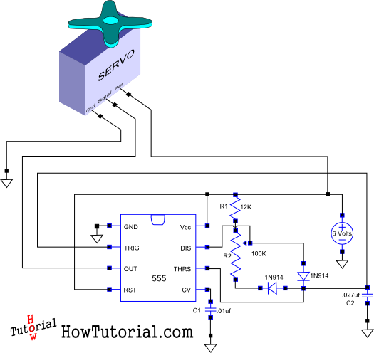
This document outlines the design of a simple circuit that enables control of a servo motor and allows for testing its functionality. The circuit for controlling a servo motor typically consists of a microcontroller, a power supply, and the servo...
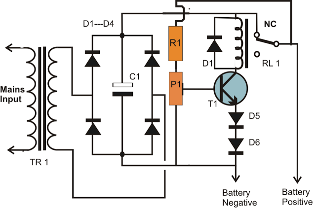
A simple battery charger circuit is described, utilizing a single transistor for voltage detection and automatically disconnecting the battery from the supply when fully charged. The circuit's high voltage trip point is set to switch off the charging voltage...
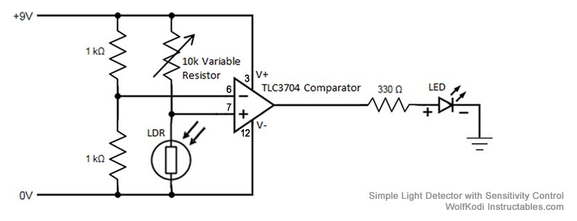
The schematic diagram for the circuit is provided in the accompanying image. As indicated by its name, a comparator is designed to compare two specified voltages. The circuit includes a pair of 1K resistors. A comparator circuit typically utilizes operational...