
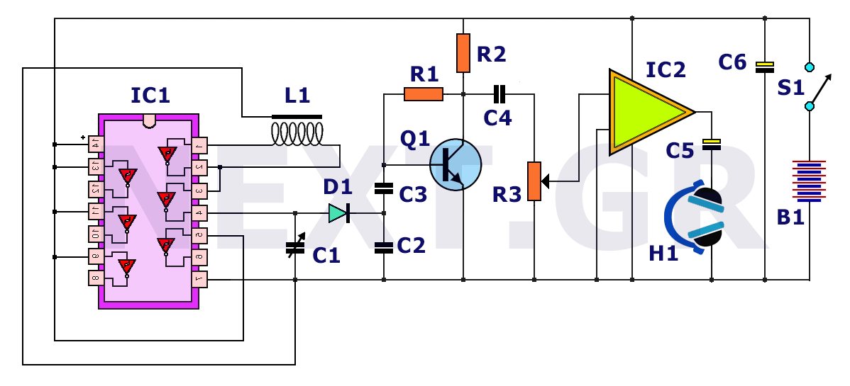
simple booster tv schematic diagram

The RF amplifier circuit designed for UHF television signals employs a tuned circuit configuration to maximize signal strength and clarity. The core components include a 15 nH inductor and a 2.2 pF capacitor, which together form a resonant circuit. This configuration is critical for effectively amplifying signals within the specified frequency range of 450-800 MHz.
The gain of approximately 10 dB indicates that the circuit can significantly improve the reception of weak signals, which is particularly beneficial in areas with poor signal strength. The choice of components is essential; the inductor and capacitor must be precisely selected to ensure that they resonate at the desired frequency. The option to substitute the 2.2 pF capacitor with a 4.7 pF capacitor or a variable trimmer capacitor allows for fine-tuning of the circuit, enabling users to adjust the resonance frequency for optimal performance based on their specific signal environment.
The simulated frequency response, generated using the TINA software, provides valuable insights into the performance of the circuit. By sweeping an input signal of 20 µV across the frequency range of 400-800 MHz, the simulation offers a graphical representation of how the circuit responds to various frequencies. The measurement into a 1 kΩ load reflects realistic operating conditions, while the 75 Ω impedance of the frequency generator aligns with standard RF practices. This simulation serves as a predictive tool, allowing engineers to assess the circuit's effectiveness before physical implementation.
Overall, this RF amplifier circuit is a practical solution for enhancing UHF television signals, combining a simple yet effective design with adjustable components to cater to varying reception conditions.This is circuit that can be used to strengthen the RF signals from a television antenna work at UHF frequencies in the range 450-800MHz. It has a gain of around 10dB and is suitable for boosting weak TV signals The tuned circuit comprising the 15nH inductor and 2.
2pF capacitor resonate in the center of the UHF band. The 2. 2pF capacitor may be Exch anged for a 4. 7pF or a Trimmer capacitor of 2-6pF to improve results. The approximate frequency response is shown below. N. B. This is a simulated response using the TINA program produced by using a swept input 20uV swept over the frequency range 400-800MHz. Output was measured into a 1k source and the frequency generator has a 75ohm impedance. 🔗 External reference
Related Circuits
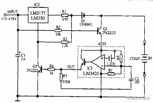
A lithium-ion battery charging circuit is illustrated above. Initially, when charging begins, if the battery voltage is below 8.4V, the output of IC1 is inactive. As a result, Q2 remains off, and the LM317 operates in constant current mode....
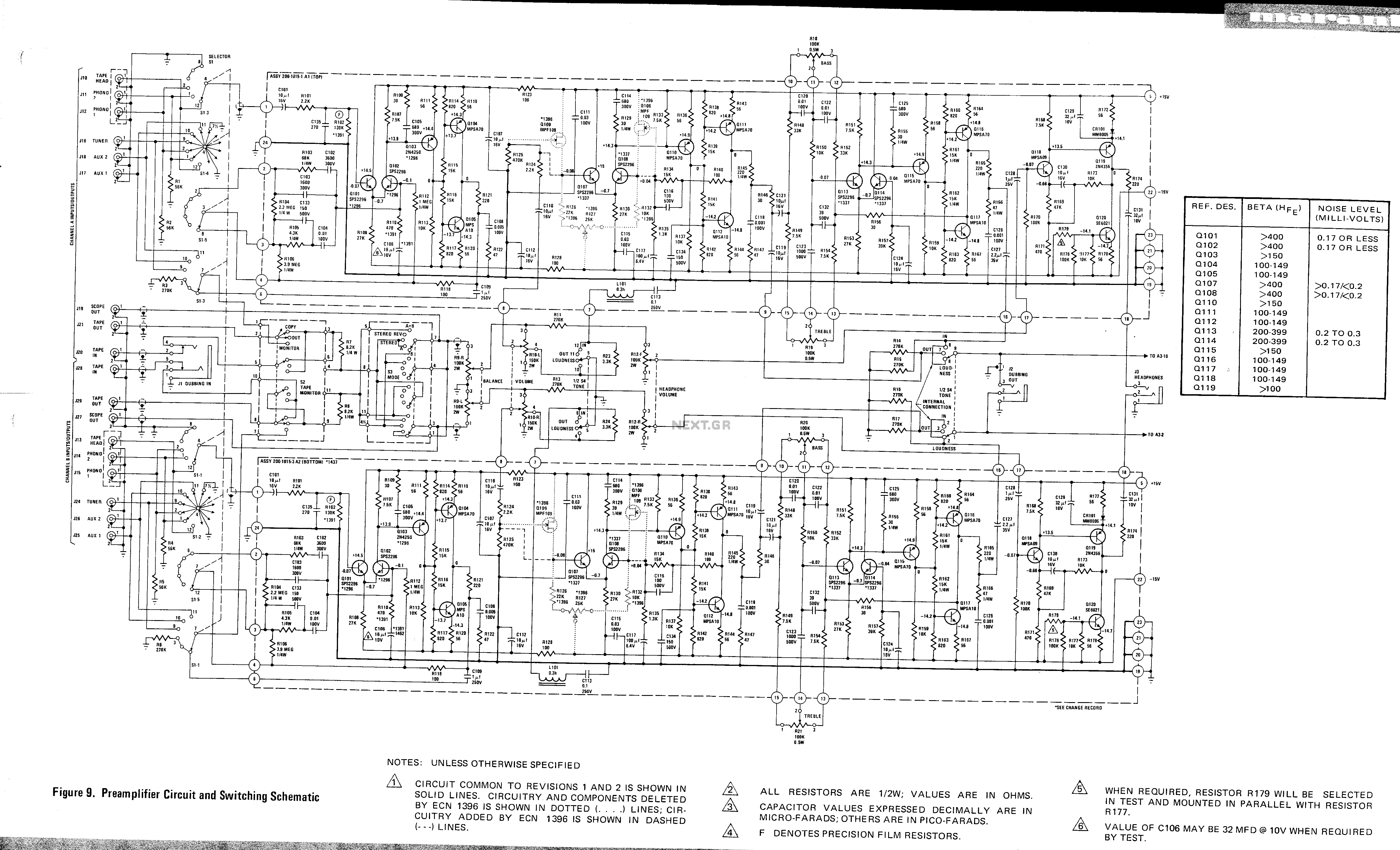
This is a preamplifier circuit and switching schematic for the Marantz Model 33. The Marantz Model 33 preamplifier circuit is designed to amplify low-level audio signals from various sources before sending them to a power amplifier. The schematic typically includes...
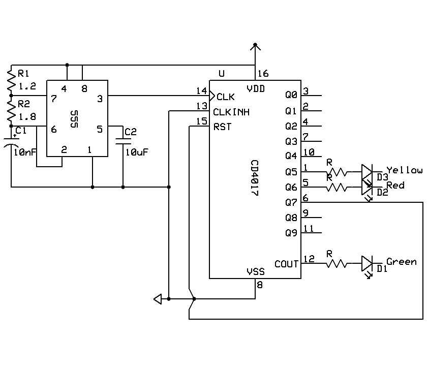
A timer is being developed for circuit training or boxing training. The timer does not require any external input, except for a reset function. The project can be simplified using a microcontroller, such as the PIC12F635, which is cost-effective...
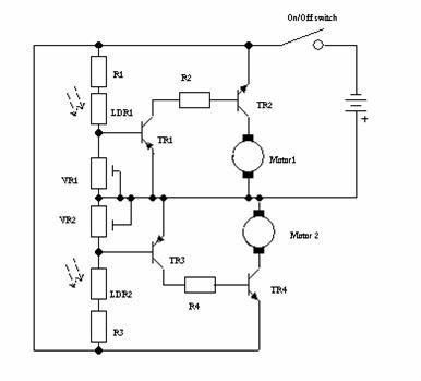
This robot was designed as a project for secondary school pupils to build during an activity day. The chassis was provided to the pupils pre-cut. The total cost of the components per robot was just under GBP 5, including...
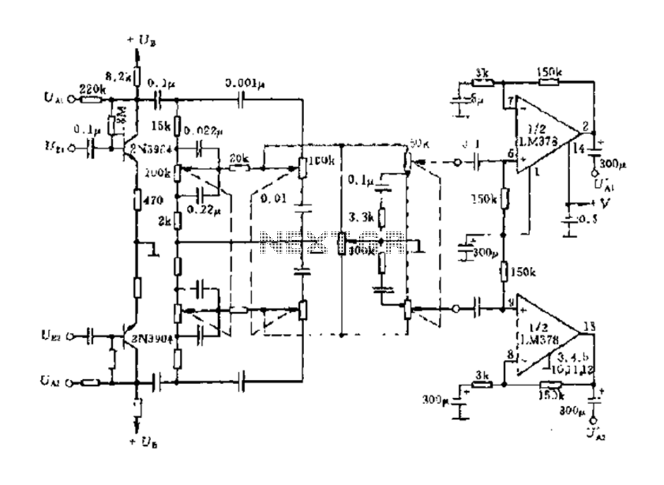
The dual-channel circuit features the LM378 dual operational amplifier and operates with a supply voltage of 24V, supporting an 8-ohm load (or 16 ohms). Each channel delivers an output power of 4W. The circuit includes internal current limiting and...
The principle behind a metal detector is quite simple. This is demonstrated by the following circuit, which shows that a metal detector can be constructed quickly with a few readily available components. This metal detector circuit can detect a...