
CD4013 Push Button CMOS Toggle Flip Flop

The circuit is designed to efficiently toggle a relay based on momentary push button inputs, utilizing a dual D flip-flop architecture for reliable state management. The CD4013 flip-flop is a versatile component, capable of handling various digital logic tasks, making it suitable for this application. By incorporating multiple push buttons in parallel, users can activate the relay from different locations, enhancing the circuit's usability in practical scenarios such as controlling lighting or appliances from multiple entry points.
The coupling capacitor (0.1 µF) plays a crucial role in ensuring that the momentary push button press generates a sufficient high signal to trigger the set line of the flip-flop. The subsequent inversion of the Q output by the upper transistor is essential for generating a controlled low reset signal, which temporarily disables the flip-flop's output and ensures that the relay does not remain activated indefinitely. The timing of the reset, approximately 400 ms, is carefully chosen to allow for a brief activation of the relay without causing unintended latching.
Debouncing is a critical aspect of the design, as mechanical switches can produce noise during actuation. The circuit's architecture mitigates this issue through the short duration of the set signal, ensuring that the flip-flop only responds to legitimate button presses.
The choice of output transistors is significant for driving loads. The 2N3904 is appropriate for higher resistance relay coils, while the 2N3053 is utilized for lower resistance applications, ensuring that the relay is activated efficiently without exceeding the current ratings of the transistors.
Additionally, the decoupling capacitor (10 µF) and the 47-ohm resistor serve a dual purpose: they stabilize the power supply against fluctuations and filter out any high-frequency noise that could affect circuit performance. The RC network connected to the SET line provides a reliable power-on reset function, ensuring that the relay remains off until the circuit is ready for operation, thereby enhancing safety and reliability in applications where the circuit may be powered on unexpectedly.The circuit below uses a CMOS dual D flip flop (CD4013) to toggle a relay or other load with a momentary push button. Several push buttons can be wired in parallel to control the relay from multiple locations. A high level from the push button is coupled to the set line through a small (0. 1uF) capacitor. The high level from the Q output is inverte d by the upper transistor and supplies a low reset level to the reset line for about 400 mS, after which time the reset line returns to a high state and resets the flip flop. The lower flip flop section is configured for toggle operation and changes state on the rising edge of the clock line or at the same time as the upper flip flop moves to the set condition.
The switch is debounced due to the short duration of the set signal relative to the long duration before the circuit is reset. The Q or Qbar outputs will only supply about 2 mA of current, so a buffer transistor or power MOSFET is needed to drive a relay coil, or lamp, or other load.
A 2N3904 or most any small signal NPN transistor can be used for relay coil resistances of 250 ohms or more. A 2N3053 or medium power (500 mA) transistor should be used for coil resistances below 250 ohms. The 47 ohm resistor and 10uF capacitor serve to decouple the circuit from the power supply and filter out any short duration noise signals that may be present.
The RC network (. 1/47K) at the SET line (pin 8) serves as a power-on reset to ensure the relay is denergized when circuit power is first applied. The reset idea was suggested by Terry Pinnell who used the circuit to control a shed light from multiple locations.
🔗 External reference
Related Circuits
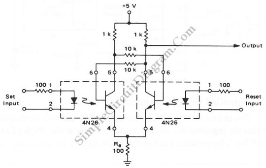
An RS flip-flop, also known as a reset-set flip-flop, is a type of stable multivibrator that has two inputs: reset and set. The output can exist in one of two stable states. The RS flip-flop is a fundamental building block...
An optical toggle switch utilizing a single chip. This design employs a dual flip-flop integrated circuit (IC) CD4027 and incorporates a 555-based monostable circuit to generate input clock pulses. The circuit outlined here eliminates the need for this configuration. The...
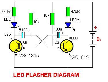
2SC1815 Flip Flop LED Flasher is a very simple and easy-to-understand circuit. The 2SC1815 Flip Flop LED Flasher circuit utilizes a 2SC1815 transistor, which is a general-purpose NPN transistor, to create a basic LED flasher. This circuit operates on the...
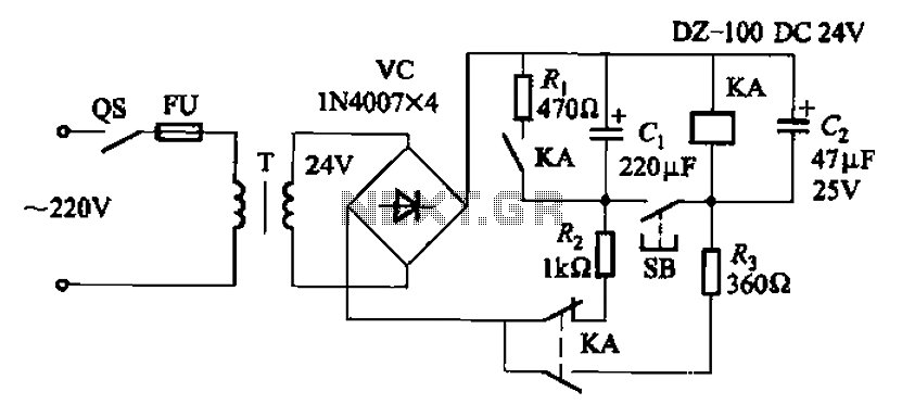
After the turn-off circuit is first applied to the next KA KA, the intermediate interval required is less than Is. This is due to the time needed, which is equal to three times the charge time constant of the...
This project is related to previous tube amplifier designs, particularly the first Push-Pull EL84 (6BQ5) Oddwatt project from nearly two years ago. Both projects utilize EL84 / 6BQ5 tubes; however, while the earlier version employed an ECC802S driver, this...

CMOS interface circuit with PMOS cross-coupled PMOS integrated circuit featuring high input impedance, where the input current can be ignored. The CMOS and PMOS interface circuit is illustrated in the accompanying figure. The CMOS interface circuit utilizing PMOS cross-coupled configurations...