
Simple calculator schematic

The schematic for the simple calculator circuit typically includes a microcontroller, a keypad for user input, and a display for output. The microcontroller serves as the central processing unit, executing the calculations based on the inputs received from the keypad. Commonly used microcontrollers for such applications include the ATmega series or PIC microcontrollers, which are capable of handling basic arithmetic operations.
The keypad is arranged in a matrix format, consisting of multiple rows and columns. When a key is pressed, it connects a specific row to a column, allowing the microcontroller to detect which key has been activated. Debouncing techniques may be implemented in the software to ensure that multiple signals are not registered from a single key press.
The output is typically displayed on a 7-segment display or an LCD screen. A 7-segment display consists of individual segments that light up to represent numbers, while an LCD can display both numbers and text. The microcontroller is connected to the display through a series of GPIO (General Purpose Input/Output) pins, which control the segments or characters to be displayed.
The PCB layout must be designed to ensure minimal interference and optimal signal integrity. Components such as resistors and capacitors may be included to manage power supply stability and to filter noise from the power lines. Additionally, proper routing of traces is crucial to avoid crosstalk and to maintain a compact design.
Power supply considerations are also essential; the circuit may operate on batteries or a regulated power supply. Voltage regulators may be used to ensure that the microcontroller and other components receive a consistent voltage level.
This simple calculator project serves as an excellent learning tool for students interested in electronics, providing hands-on experience in circuit design, PCB layout, and programming microcontrollers.In this document is a simple calculator and PCB circuit board wiring diagram, simple, interested students can design their own!
Related Circuits
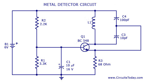
A simple metal detector circuit diagram and schematic using a single transistor and a radio. This metal detector/sensor project is easy to make and is an application of a Colpitts oscillator. The metal detector circuit utilizes a single transistor in...

The complete hardware schematic of the Night Light Saver V6.0 includes an AC line protected by a 1A fuse (F1). Any short circuit caused by the components of the saver will blow the fuse. Resistor R1 and capacitor C1...
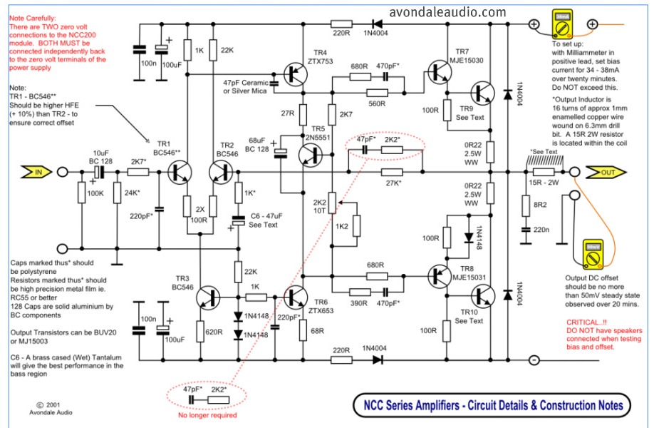
This is a simple circuit that features high-performance power amplifiers. The power amplifier is available as a PCB, along with a complete list of components. The described circuit utilizes high-performance power amplifiers, which are essential for applications requiring significant signal...

This is a simple and low-cost NiCd and NiMH battery charger. The schematic diagram indicates that the charging current (I) should be set to 1/10 of the battery's rated capacity. For instance, if the battery has a rated capacity...
The two resistors serve dual purposes. Firstly, they limit the current to a lower value in case of accidental contact with the circuit. Secondly, when the flash is activated, the main capacitor behaves like a short circuit to the...
The objective is to enhance information transmission by utilizing articles. Please contact us via email at [email protected] within 15 days if there are issues related to article content, copyright, or other concerns. Prompt action will be taken to resolve...