
Simple Cat.5 Network Tester

This network tester circuit is designed to provide a straightforward solution for testing network connectivity and diagnosing issues in a network environment. The circuit typically includes a signal generator, a receiver, and indicator LEDs to convey the status of the network connection.
The signal generator can be implemented using a simple oscillator circuit, which produces a specific frequency signal that can be transmitted over the network. This signal is then picked up by the receiver portion of the circuit, which may consist of an operational amplifier configured as a comparator. The output of the receiver will drive an LED indicator, which illuminates when a valid signal is detected, signaling that the network connection is functioning as expected.
Power supply considerations for this circuit are essential; typically, a battery or a regulated power supply is used to ensure stable operation. The circuit can be designed to consume minimal power to extend battery life, making it suitable for field use.
To enhance usability, the circuit may incorporate a simple user interface, such as a single button to initiate the test process, allowing one person to operate the device easily. Additional features, such as a buzzer or an LCD display, can be added to provide audible or visual feedback regarding the test results.
Overall, this network tester circuit is a practical tool for quick diagnostics in networking applications, facilitating efficient troubleshooting and maintenance of network systems in various environments.This circuit came from a need for a quick and dirty network tester that could be operated by one person. All the commercial units I tried required a per.. 🔗 External reference
Related Circuits
To put the relay in tension the 4 buttons S1 S4 must be pressed. If anyone of the 4 buttons S5 S8 are pushed the relay doesn't tension (doesn't receive supply voltage). The supply voltage must be equal to...
The 555 IC is configured as an astable multivibrator, producing a constant frequency independent of the duty cycle. The total resistance (R_charge + R_discharge, with the diode in consideration) remains constant at 22 kΩ, resulting in a frequency of...
This simple circuit generates a good and stable 1V peak-to-peak square wave at 100Hz, 1KHz and 10KHz using a single 1.5V cell as power supply. An useful feature of this circuit is that frequency changes can be obtained by...
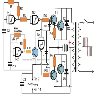
The PWM-controlled modified sine wave inverter circuit presented here utilizes a single 4093 integrated circuit (IC) for its specified functions. This IC consists of four NAND gates, with two configured as oscillators and the other two serving as buffers....

A good/bad transistor tester is an instrument designed to determine the operational status of a transistor, indicating whether it is functional or defective. This device provides a simple binary assessment, confirming if the transistor has a gain equal to...
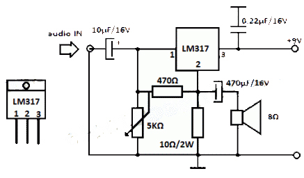
The LM317 integrated circuit (IC) is commonly recognized as a voltage regulator; however, it can also function as an audio amplifier. This low-power amplifier circuit designed with the LM317 provides a maximum output of approximately 1 watt. The LM317...