
simple circuit mini bicycle bel

The mini bicycle bell circuit operates at a nominal voltage of 9V, which is supplied by a standard battery. The circuit employs two transistors, Q1 and Q2, which function as electronic switches. Q1 is responsible for controlling the flow of current when the button is pressed, allowing the circuit to be activated. This activation results in a current being directed to Q2, which in turn powers the speakers.
The use of a capacitor in the circuit serves a crucial role in sound modulation. It acts as a filter that smooths out the electrical signal sent to the speakers, preventing abrupt cessation of sound when the button is released. This capacitor effectively allows for a gradual decay of sound, enhancing the auditory experience.
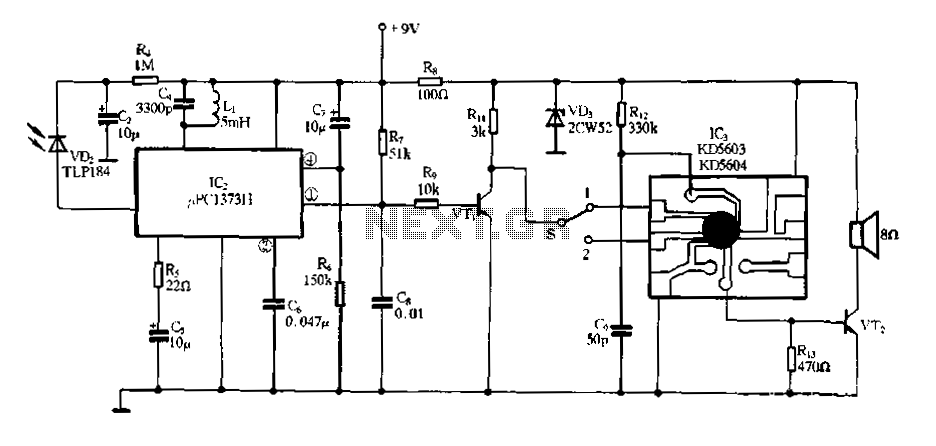
The schematic diagram provided illustrates the connections between the components, including the power supply, transistors, speakers, and the capacitor. The design is straightforward, making it suitable for hobbyists and those looking to create a simple yet effective bell system for bicycles.
For those interested in further modifications, the circuit allows for the substitution of the mechanical switch S1 with a proximity sensor. This change would enable the bell to activate without direct contact, providing a more modern and user-friendly approach. The PCB design accompanying the circuit simplifies the assembly process, allowing for a more organized and reliable construction of the mini bicycle bell. The downloadable PCB layout ensures that users can replicate the circuit with precision, facilitating ease of use for both novice and experienced electronics enthusiasts.This circuit is a mini bicycle bell. Mini bicycle bell is connected using the bell as a switch. If the button is pressed, an electric current flowing on the 9V voltage electronic circuit through the transistor Q1. because the speakers are connected to the battery using a transistor Q2, when the transistor electrified, the speakers will also be ele
ctrified and sounds. Capacitor is used to the sound of the speakers is not a quick stop. Here is a schematic drawing mini bicycle bell: For the development of this circuit you can replace the switch S1 with the proximity sensor circuit. here I also include a PCB (printed circuit board) of the simple circuit mini bicycle bell and you can also download it.
🔗 External reference
Related Circuits
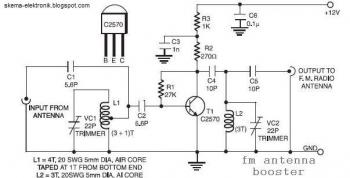
The input coil L1 is composed of four turns of 20 SWG enamelled copper wire, wound slightly spaced over a 5 mm diameter former. It is tapped at the first turn from the ground lead side. Coil L2 is...
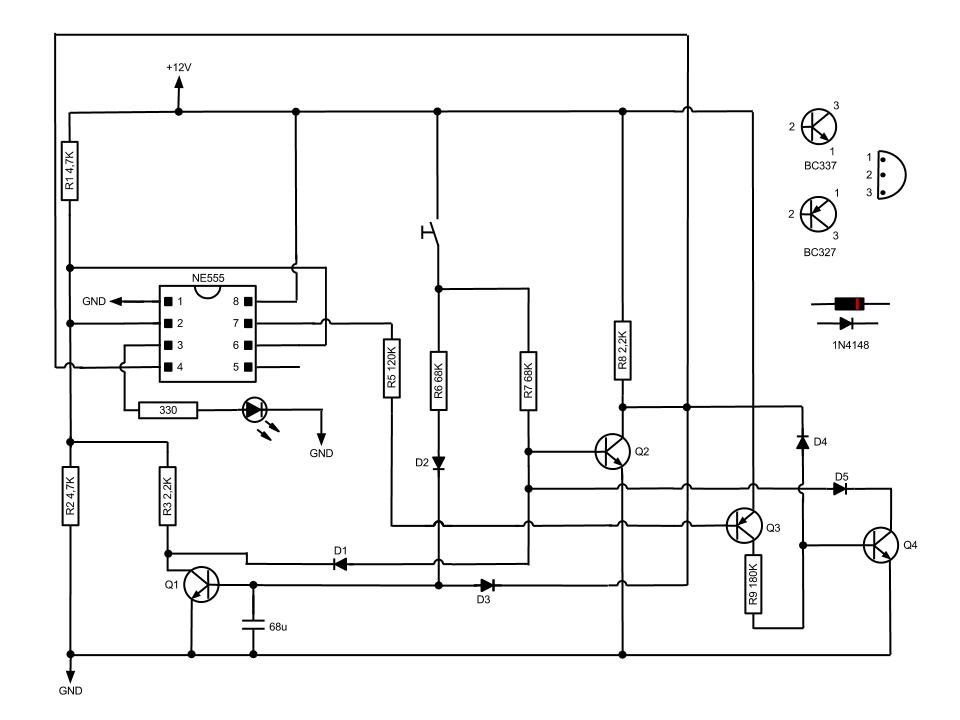
This circuit, based on the NE555 timer IC, toggles the output on and off using a momentary switch. It functions similarly to a mechanical latching relay but resets to its initial state when the power supply is turned off....
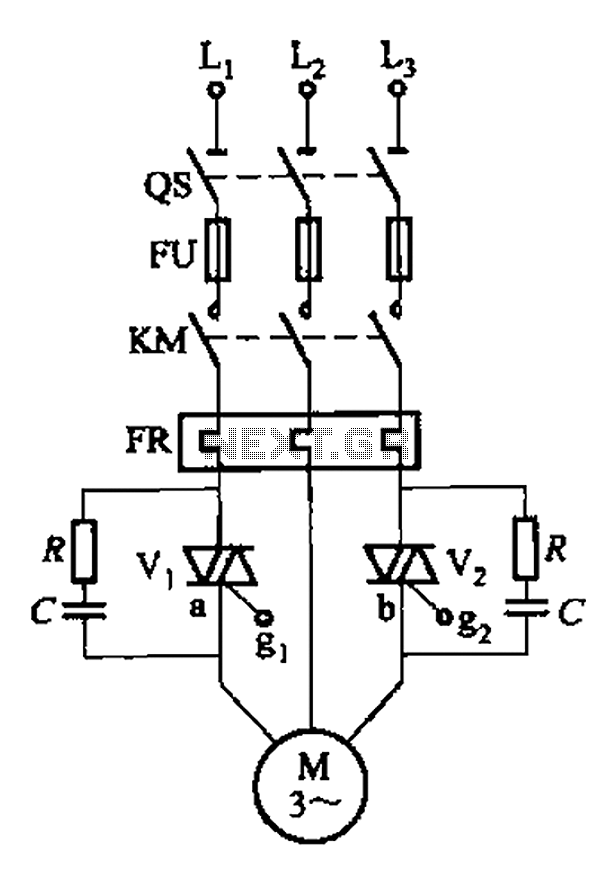
The circuit depicted in Figure 3-80 is responsible for controlling a portion of the transistor multivibrator. A multivibrator serves as a robust positive and negative feed-forward amplifier, consisting of two branches that are interconnected through a coupled RC timing...

This document illustrates the configuration of the high-precision, high-impedance OPA2111 amplifier. The total voltage circuit is designed for a magnification of Av = 10 (1 + 2R2 / R1), achieving a total gain of 1000 times. A gain stage...
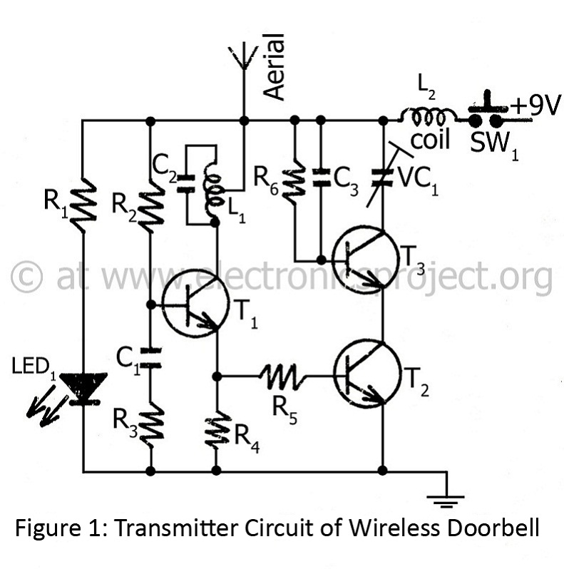
The controlling range of the wireless doorbell is 100 meters. The transmitter section is designed around an oscillator transistor (BF194B) T2, which is followed by two transistors (BC148) T1 and T3. Transistor T2 generates a specific radio frequency determined...
Electronic Miss Manners infrared receiver and voice circuits The Electronic Miss Manners system integrates an infrared (IR) receiver with voice circuits to facilitate communication and interaction. The IR receiver is designed to detect signals emitted from a remote control or...