
simple digital counter by

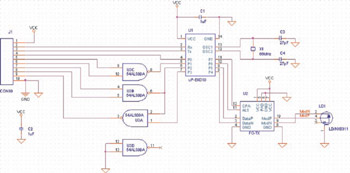
The circuit design integrates essential digital components, including flip-flops and counters, to facilitate event counting and frequency measurement. The use of a 4029 BCD counter IC allows for efficient binary-coded decimal output, which is crucial for applications requiring numerical display. The seven-segment display provides a user-friendly interface for visualizing the decimal output, enhancing usability.
The configuration of the DIP switch enables users to set specific values, which are then processed by the counter. The incorporation of a clock pulse generator, realized through a NAND gate oscillator, ensures that the counter operates continuously at a defined frequency until manually interrupted. This feature is particularly useful for applications requiring real-time counting.
Capacitors are strategically placed throughout the circuit to stabilize power supply voltages and filter out noise, which is critical for maintaining the integrity of digital signals. The 0.1 µF ceramic capacitors serve to decouple the power supply from transient spikes, thereby enhancing the reliability of the circuit during operation.
Overall, this design exemplifies a practical approach to digital counting applications, showcasing the integration of fundamental electronic components with an emphasis on stability and user interaction.The basic digital circuits are Flip Flop and Counter, both are here. This circuit can be cascaded to make even a 6 digit event counter, even a simple frequency counter can be made. These are best done with microcontrollers today. Then what if you have to design your own microcontroller on a FPGA, so the basics have to be sound, hence you have to k
now what gates, flip flops and counters are. a. Set the DIP Switch as you like and then Press the Set button. The BCD value will be at the 4029 output, The Decimal value will be seen in the seven segment Display. Now try for different dip switch settings and see the BCD and Decimal output. c. Now Click the Clk - clock or count button, the switch will latch, press it again to release. If you toggle it once the counter will get a single pulse and it will count it, see the BCD and decimal displays.
Now you turn it on and leave it, the counter will keep counting one per second till you turn it off, the clock nand gate is wired to be an oscillator. Add 104 CD, 0. 1uF ceramic disc cap to all the ICs across the supply pins. Also add a 104 CD cap across Inc switch and one across the Set switch for power on default settings 🔗 External reference
Related Circuits
The advanced credit card, referred to as the "microcontroller super card," incorporates numerous innovative enhancements. The initial step involved verifying the code and subsequently uploading it to the Arduino board. The developed code enabled a counter to increment from...
This unit is an upgrade of the previous phone call interceptor. Instead of using an answering machine to provide the outgoing message and recording functions, it uses the ISD4004 (from Windbond Electronics). The ISD4004 records up to 8 minutes...
This example illustrates the process of stacking layers and designing transmission lines for a high-speed digital printed circuit board (PCB). It also shows how to create a moated ground area with a bridge around a high-frequency crystal oscillator, perform...
The most common application for the NTC thermistor is temperature measurement. Accurate temperature measurement can easily be accomplished by interfacing a Wheatstone Bridge, 6K/30K ohm thermistor network and a digital voltmeter integrated circuit as illustrated in Figure 5. The...
A follow up Mk2 version described by EA's Jim Rowe in the May/June/July 94 issues of EA improved on the original with calibrated time and vertical scales, and extra triggering features. This design proved even more popular than the...
The circuit will come handy when you have to follow the mains wires buried in the wall or even water pipes provided they are not too far away (2-4cm max). It will also detect a conversation on a telephone...