
simple dimmer circuit

The described circuit employs a triac as a key component for controlling the power supplied to a load, such as a tungsten or LED lamp. The operation begins with the potentiometer, which adjusts the resistance in the circuit. This adjustment influences the charge time of capacitor C4, which is critical for the timing of the firing pulse. The resistors R3, R4, and R5, along with the potentiometer P1, form a voltage divider network that determines the charging rate of C4.
Once the voltage across C4 reaches a threshold level, the diac D transitions from a non-conductive to a conductive state. This transition generates a pulse that triggers the gate of the triac. The triac, once triggered, enters a conductive state and allows current to flow to the load, effectively controlling the power delivered to the lamp. The design enables smooth dimming of the light output by varying the phase angle of the AC waveform delivered to the lamp.
The circuit's performance can be affected by the values of the resistors and the capacitor, which need to be carefully selected to achieve the desired dimming range and response time. Additionally, the characteristics of the lamp (tungsten or LED) will influence the overall behavior of the circuit, particularly regarding the minimum load required for stable operation. Proper thermal management and component ratings are essential to ensure reliability and prevent overheating during extended use.A potentiometer is controlling the firing point of the triac. Capacitor C4 is charged via resistors R3, R4, P1, and R5. After a certain time, dependant on the potentiometer, the charge contained in C4 is large enough for the dimmers diac D to start conducting, so that a firing pulse is applied to the gate of the triac. Consequently the triac conducts and power is transferred from the dimmer to the tungsten or LED lamp.
. 🔗 External reference
Related Circuits
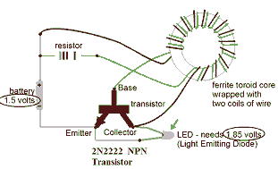
This circuit is known as the Joule Thief. For those unfamiliar with it, an image of the circuit is provided. The Joule Thief is a minimalist circuit designed to extract usable voltage from a low-voltage power source, such as a...
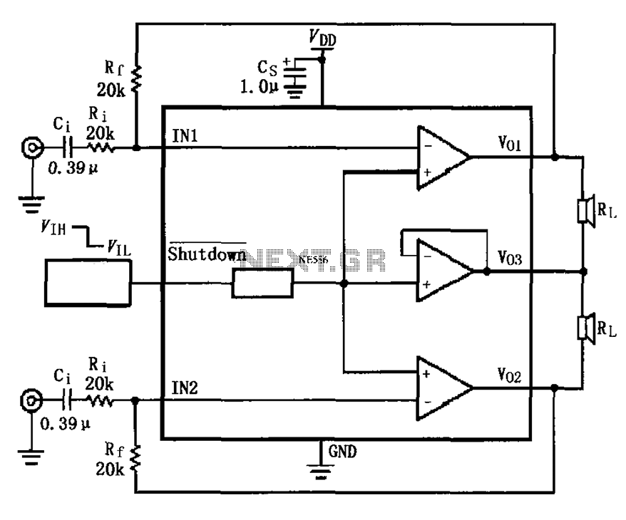
The LM4910 typical circuit is designed for a two-channel amplifier. The left and right channel audio signals are input to the LM4910 (in an MSOP/SO package) at pins 1 and 2. The output signals are delivered from pins 6,...
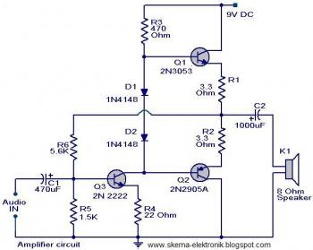
The initial section of the circuit is a preamplifier that utilizes transistor Q1 (2N2222). The collector of transistor Q3 is connected to the base of transistor Q2 (2N2905A), which creates a complementary symmetry pair with Q3 (2N3053). The amplified...
Infrared remote controls are using a 32-56 kHz modulated square wave for communication. These circuits are used to transmit a 1-4 kHz digital signal (OOK modulation) through infra light (this is the maximum attainable speed, 1000-4000 bits per sec)....

This system operates on the principle that the capacitance loading of an oscillator will lower its frequency. When a foreign body comes into contact with the touch plate, the frequency of U1 is lowered. This removes the oscillator signal...
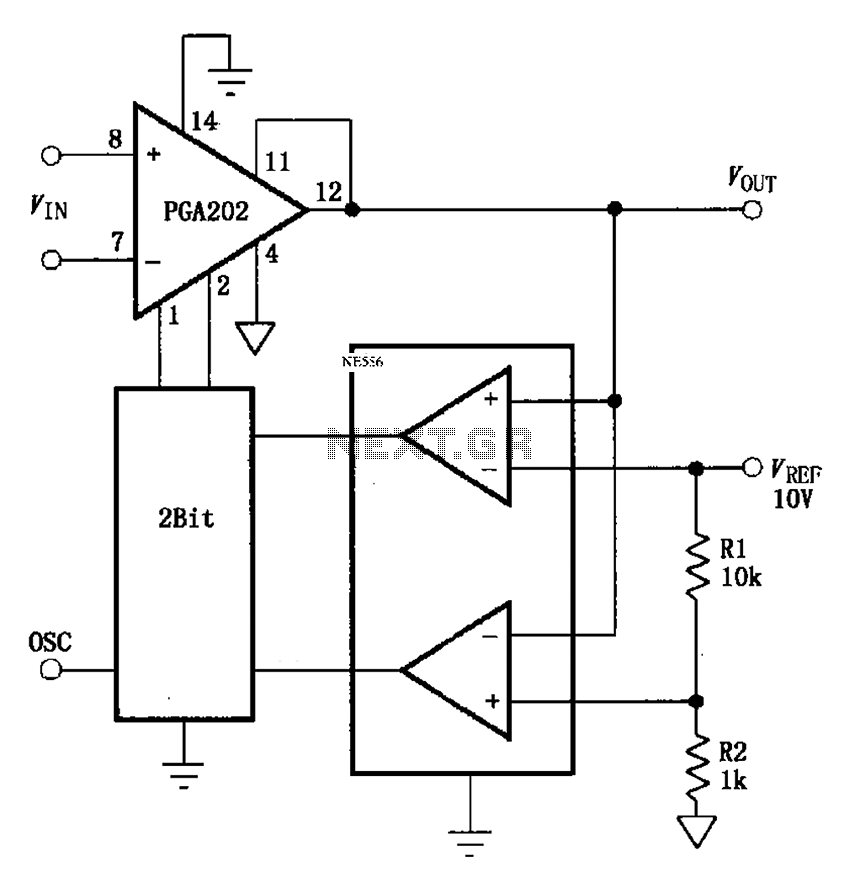
The automatic range switching circuit consists of PGA202, comparators, and counters, as illustrated in the figure. The comparator at the output compares VOUT with VREF. When VOUT exceeds 10V, the comparator generates a low signal, causing the up/down counter...