
Simple Electrification Unit

The circuit operates by utilizing a feedback mechanism that enables the generation of high-voltage pulses while maintaining safety. The design incorporates a feedback loop facilitated by operational amplifier IC1a, which stabilizes the pulse repetition frequency through the time constant defined by resistor R1 and capacitor C3. This configuration allows the circuit to produce a consistent output frequency suitable for experimental applications.
The transformation of the rectangular waveform into sharp pulses by operational amplifier IC1b is critical for driving the thyristor. The differentiating network formed by R2 and C4 plays a vital role in shaping the pulse width, ensuring that the output is optimized for triggering the thyristor effectively.
The use of a small mains transformer as a high-voltage generator is a noteworthy aspect of this circuit. By repurposing the secondary winding as the primary, the design achieves a compact form factor while still delivering substantial voltage. The resonant characteristics of the transformer, combined with the timing of the capacitor discharges, enable the circuit to produce dual voltage spikes, enhancing the experimental versatility.
The inclusion of diodes, such as D1, serves to manage current flow and protect the circuit components. The reverse-biasing of D1 during the discharge phase of capacitor C2 is a critical function that ensures safe operation by preventing backflow of current, thereby maintaining the integrity of the circuit.
Overall, this circuit exemplifies an efficient design approach for generating high-voltage pulses for experimental purposes, balancing performance with safety considerations. The careful selection of components and their arrangement allows for reliable operation while minimizing risks associated with high-voltage applications.The circuit is intended for carrying out harmless experiments with high-voltage pulses and functions in a similar way as an electrified fence generator. The p. r. f. (pulse repetition frequency) is determined by the time constant of network R1-C3 in the feedback loop of op amp IC1a: with values as specified, it is about 0.
5 Hz. The stage following t he op amp, IC1b, converts the rectangular signal into narrow pulses. Differentiating network R2-C4, in conjunction with the switching threshold of the Schmitt trigger inputs of IC1b, determines the pulse period, which here is about 1. 5 ms. The output of IC1b is linked directly to the gate of thyristor THR1, so that this device is triggered by the pulses.
The requisite high voltage is generated with the aid of a small mains transformer, whose secondary winding is here used as the primary. This winding, in conjunction with C2, forms a resonant circuit. Capacitor C3 is charged to the supply voltage (12 V) via R3. When a pulse output by IC1b triggers the thyristor, the capacitor is discharged via the secondary winding.
The energy stored in the capacitor is, however, not lost, but is stored in the magnetic field produced by the transformer when current flows through it. When the capacitor is discharged, the current ceases, whereupon the magnetic field collapses. This induces a counter e. m. f. in the transformer winding which opposes the voltage earlier applied to the transformer. This means that the direction of the current remains the same. However, capacitor C2 is now charged in the opposite sense, so that the potential across it is negative.
When the magnetic field of the transformer has returned the stored energy to the capacitor, the direction of the current reverses, and the negatively charged capacitor is discharged via D1 and the secondary winding of the transformer. As soon as the capacitor begins to be discharged, there is no current through the thyristor, which therefore switches off.
When C2 is discharged further, diode D1 is reverse-biased, so that the current loop to the transformer is broken, whereupon the capacitor is charged to 12 V again via R3. At the next pulse from IC1b, this process repeats itself. Since the transformer after each discharge of the capacitor at its primary induces not only a primary, but also a secondary voltage, each triggering of the thyristor causes two closely spaced voltage pulses of opposite polarity.
These induced voltages at the secondary, that is, the 230 V, winding, of the transformer are, owing to the higher turns ratio, much higher than those at the primary side and may reach several hundred volts. However, since the energy stored in capacitor C2 is relatively small (the current drain is only about 2 mA), the output voltage cannot harm man or animal.
It is sufficient, however, to cause a clearly discernible muscle convulsion. 🔗 External reference
Related Circuits
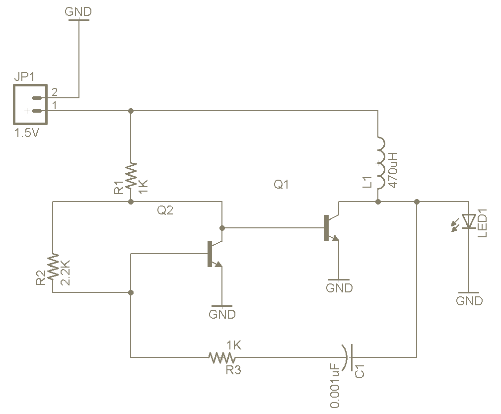
The Joule Thief is a straightforward and uncomplicated device, yet its functionality is remarkable. It can utilize a battery that is otherwise deemed unusable in any other electronic device, and it is very easy to construct on a breadboard...
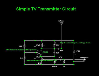
Many individuals inquire about TV transmitters. This document provides a useful circuit diagram that enables signal transmission over distances of 75 to 100 meters. The circuit diagram is not original but was provided by a colleague. Contributions of circuit...
The circuit diagram represents a simple yet effective intercom system entirely based on transistors. It consists of three stages along with an RC amplifier. When the pushbutton S2 is pressed, the amplifier circuit around transistor T1 is activated. The intercom...

Generating sine waves with controlled frequencies over a wide range is challenging when using RC or LC sinusoidal oscillators. However, this can be effectively achieved using a wideband digital square wave oscillator, a counter, and a weighted summing network....
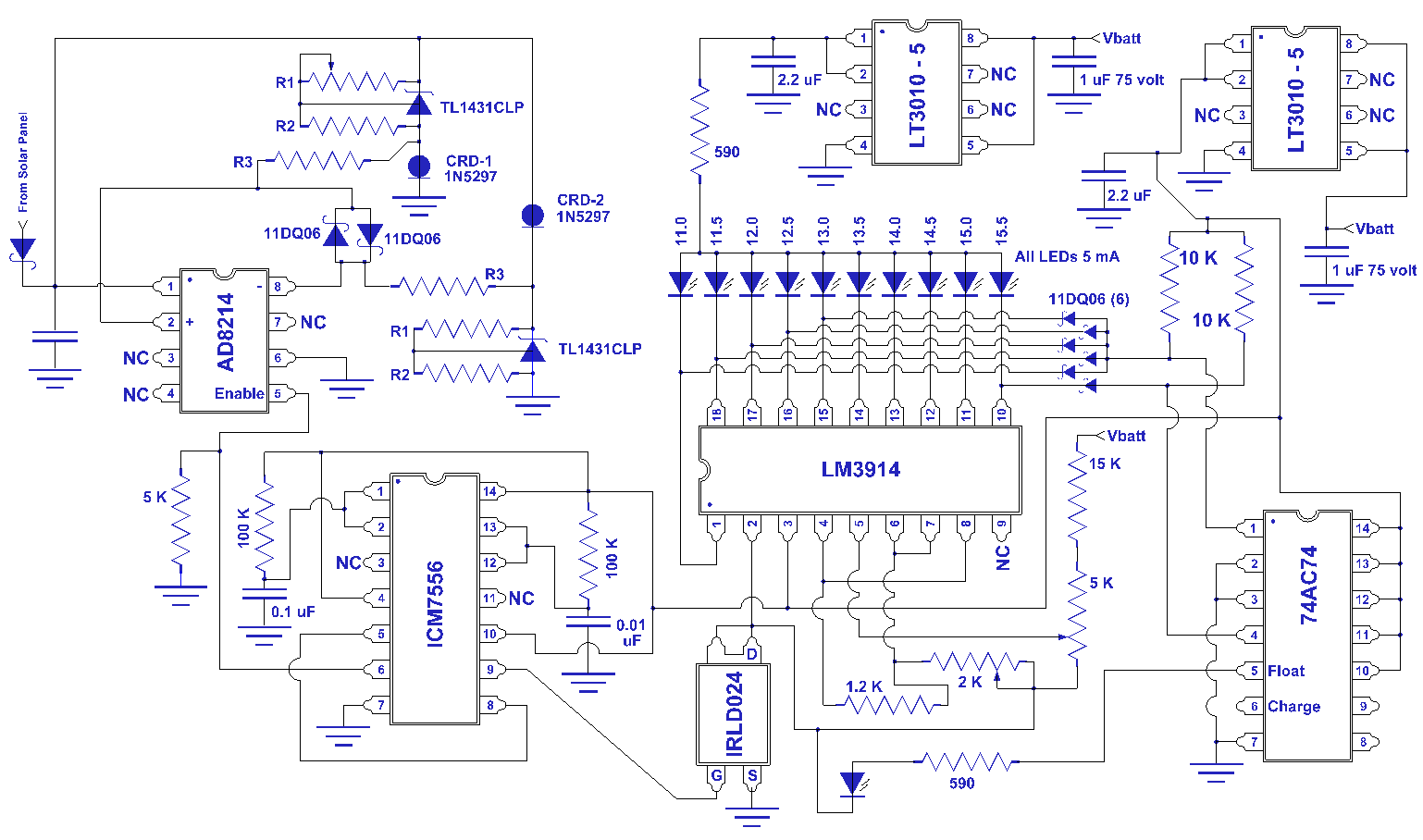
I have been researching the appropriate voltages for charging, particularly regarding this topic. The proper voltage levels for charging various types of batteries are critical for ensuring efficiency and longevity. For instance, lithium-ion batteries typically require a charging voltage of...
The first two components are passive elements, while the operational amplifier (op-amp) is an active element. The passive elements are two-terminal components, whereas the op-amp is a three-terminal component. A resistor controls the current flowing through it when a...