
Simple Intercom Circuit Transistor

The intercom circuit utilizes three transistor stages to amplify audio signals, ensuring clear communication between the stations. The first stage typically involves a microphone connected to the base of the first transistor (T1), which serves as a pre-amplifier. This stage is crucial for picking up the audio signals and converting them into electrical signals.
The second stage amplifies the signal further, using a second transistor (T2) configured in a common emitter arrangement. This configuration provides additional gain and helps to drive the next stage of the circuit. The output from T2 is then fed into an RC (resistor-capacitor) filter that smooths out the signal and eliminates any high-frequency noise that may interfere with audio clarity.
The final stage, which involves the third transistor (T3), acts as a driver stage to power the speaker or output device. This transistor also ensures that the audio signal is strong enough to be heard clearly at the receiving end of the intercom system. The pushbutton switch S2 serves as a control mechanism, allowing the user to activate the circuit and initiate communication.
In summary, this transistor-based intercom circuit design effectively amplifies audio signals through a three-stage amplification process, with the RC filter enhancing signal quality, making it suitable for reliable intercom applications.Circuit diagram is a simple but effective circuit intercom circuit is based entirely on transistors. Circuit diagram is based on three stages plus RC amplifier. When the pushbutton S2 is pressed, the amplifier cord around T1 . 🔗 External reference
Related Circuits
Due to the varying conditions of different input signals, when an abnormal voltage is applied to the pin, protection circuits are designed to create a circuit path that secures the internal protection of large-scale integration (LSI) circuits. The structure...

This metal detector circuit project is a simple design based on common electronic components. It utilizes transistors to provide a visual indication through an LED and an acoustic signal to alert users when metal is detected. To calibrate the...
The light from a flashlight is directed at a phototube, which activates a CMOS logic circuit powered by a battery. This circuit controls the switching action to turn the motor of a model train or other electric toys on...
The thermistor network specified eliminates the need for a linearity trim at the expense of accuracy and operational range. The thermistor network is designed to provide a simplified approach to temperature measurement and compensation by negating the requirement for linearity...
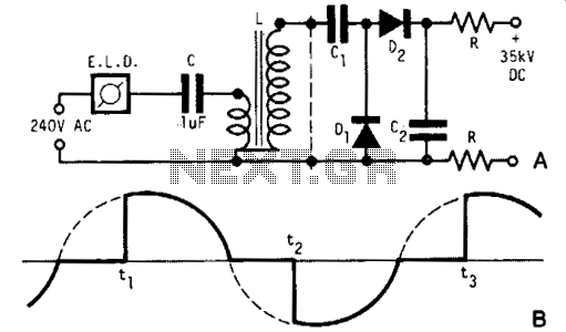
A light dimmer, a 1 µF capacitor, and a 12 V car ignition coil form a simple line-powered high-voltage generator. The current in the dimmer is illustrated in Fig. B. During the time intervals tp to t2, determined by...

This circuit diagram is a simple and effective design for amplifying weak signals from a capacitive condenser microphone. It is suitable for sound sensing applications and various automatic robotic sensors. While a more complex audio amplifier circuit using the...