
simple emergency led light circuit

The emergency LED light circuit is designed to operate under conditions where the main power supply is disrupted. The circuit begins with a 220V AC input, which is transformed down to 12V DC using a suitable transformer and rectifier configuration. This 12V output is then fed into an LM317 voltage regulator, which is configured to output a stable 7.37V. The LM317 requires two resistors for voltage setting: a fixed 240-ohm resistor and a variable resistor (typically 1.2K ohms) to fine-tune the output voltage.
When the main power supply is available, the LED indicator remains off, and the battery is charged. The circuit ensures that the transistor Q1 remains in the off state during this charging phase, preventing any current from flowing to the LED array. The LED indicator serves a dual purpose: it illuminates when the battery is charging and confirms that Q1 is not conducting.
Upon detection of a voltage drop, such as during a brownout, the transistor Q1 is activated, allowing current to flow to the 16 white LEDs connected in parallel. Each LED draws approximately 20 mA, resulting in a total current draw of about 320 mA when all LEDs are illuminated. The circuit is designed to utilize a 6V, 4.5Ah rechargeable battery, which can sustain the LED operation for up to 14 hours when fully charged.
This emergency LED light circuit is effective for providing illumination during power outages, ensuring safety and visibility. The simplicity of the design and the availability of components make it an excellent project for both novice and experienced electronics enthusiasts.This emergency LED light is simple, inexpensive and easy to build. The circuit to the battery and when the main source is not available, such as brownouts, white LEDs turns on automatically. Initially, the output voltage from 220V to 12V converter is fed to the input of LM317 regulator. Then, this voltage is regulated to 7. 37V with 240 ohms and th e combination of the resistance of 1. 2K (see LM317 Calculator). At this time, the battery is in charging mode and the transistor Q1 is off. LED serves two purposes, one is mainly to give us an idea of the battery is charging and the other is to ensure that Q1 is off. During voltage drops, the transistor Q1 is on and supplies the current to 16 white LED of about 20 mA each, so a fully charged battery (6V/4.
5Ah) may last up to 14 hours. 🔗 External reference
Related Circuits
Modern acid batteries and lead plates are embodiments of simplicity in use. Unlike NiCd batteries, they must be recharged by connecting to a constant voltage source. Modern acid batteries, commonly referred to as lead-acid batteries, consist of lead plates submerged...

An audio power amplifier circuit for a 3-watt stereo amplifier using the MAX 7910 IC is explained below. The audio power amplifier circuit utilizing the MAX 7910 IC is designed to deliver a maximum output power of 3 watts per...
This circuit is a digital voltmeter diagram featuring an LED display. It is designed for measuring the output voltage of a DC power supply. The voltmeter incorporates a 3.5-digit LED display along with a negative voltage indicator. It is...
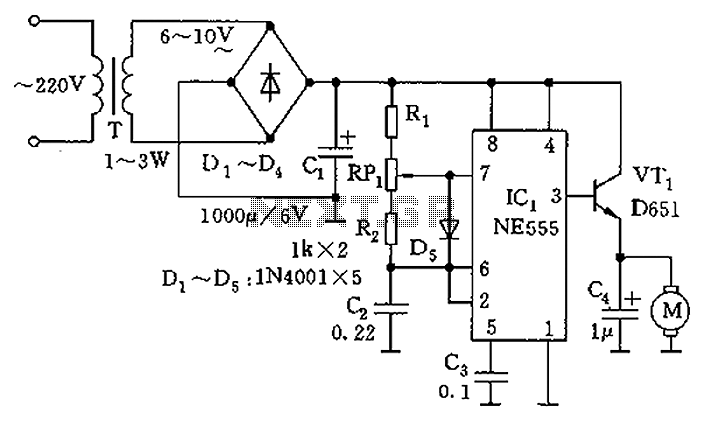
The circuit utilizes a 555 timer as the core component to create an astable multivibrator. The oscillation period T is given by the formula T = 0.693 (R1 + 2R2) C1, which corresponds to an oscillation frequency of approximately...
Building a personal alarm system is both practical and engaging. The most rewarding aspect is demonstrating its functionality to friends by activating the alarm remotely, saying, "I completed this in a weekend." Customizing the alarm system offers maximum flexibility,...
This heatsink temperature monitor circuit uses three LEDs to signal when the temperature exceeds two boundary levels. When the heatsink temperature is below 50-60°C (122-140°F), the green LED lights up. The yellow LED indicates that the temperature is between...