
Simple Field Strength Meter

The described circuit utilizes a digital multimeter (DMM) for measuring low voltage signals, particularly in VHF applications. The choice of setting the DMM to the 200mV DC range is crucial for achieving maximum sensitivity, allowing for the detection of subtle voltage changes that may occur at high frequencies, such as those in the VHF spectrum.
The inductor L1, constructed with 7 turns on a quarter-inch former and incorporating a ferrite slug, is designed to resonate at the desired frequency range, specifically covering the UK FM band. The physical dimensions and materials used in L1 contribute to its inductance and quality factor, which are critical for effective signal reception and processing. The ferrite slug enhances the magnetic permeability of the inductor, improving its efficiency in the intended frequency range.
The advantages of utilizing a digital multimeter over an analog meter in this application cannot be overstated. The high input impedance of the DMM, typically around 10 Megohms per volt, ensures that the measurement does not load the circuit significantly, thereby preserving the integrity of the tank circuit. This is particularly important in RF applications where loading can significantly affect performance.
Additionally, the ability of a digital meter to display minute variations in signal strength provides a more precise measurement, which is essential for tuning and troubleshooting RF circuits. The improved linearity of digital meters allows for accurate readings across a wide range of signal strengths, making it easier to identify and analyze both weak and strong signals without distortion or loss of information.
Overall, the integration of a digital multimeter into this VHF circuit enhances the measurement capabilities, providing reliable and sensitive readings that are essential for effective circuit performance and analysis.The multimeter should be set to the lowest dc volts range for maximum sensitivity. This is normally 200mV DC for most meters. The circuit works well at VHF (around 100MHz) and was quite pleased with the results. L1 was 7 turns on a quarter inch former with ferrite slug. This covered the UK FM band. A digital multimeter, as opposed to an analogue s ignal meter offers several advantages in this circuit. First, the impedance of a digital meter is very high, around 10Meg/Volt on most meters. This does not shunt the tank circuit unduly. Second, compared to an analogue meter, very slight differences in signal strength can be more easily observed. Thirdly, a digital meter will have better linearity, responding well to both weak and stronger signals.
🔗 External reference
Related Circuits
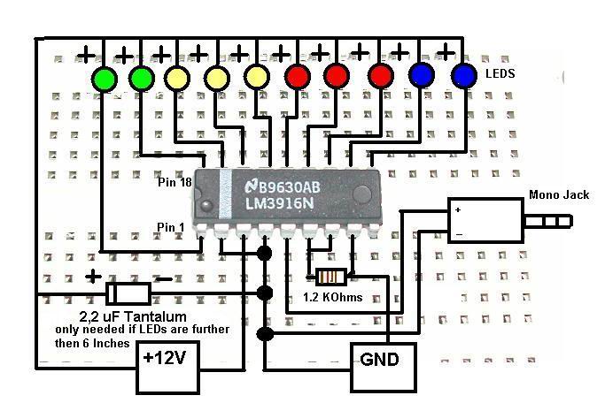
This is a concise guide for constructing a stereo VU meter utilizing the LM3915/LM3916 integrated circuits. The LM3916 is designed to convert analog voltage levels into visual representations through the activation of 10 LEDs, LCDs, or vacuum fluorescent displays,...
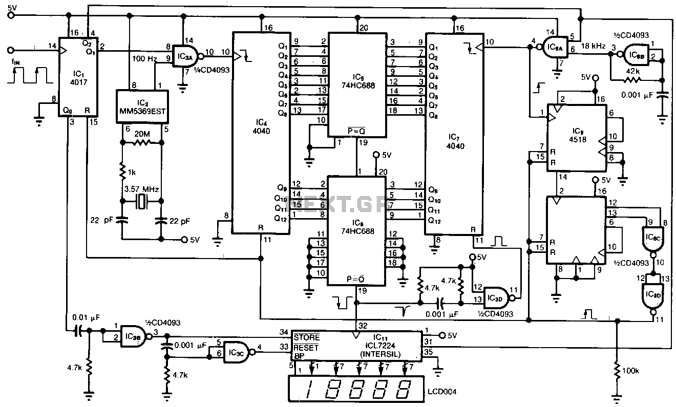
This tachometer allows for the measurement of heartbeats, respiratory rates, and other low-frequency events that occur at intervals ranging from 0.33 to 40.96 seconds. The circuit detects the frequency, calculates the corresponding pulses per minute, and updates the LCD...
This relatively simple mixer was designed for three dynamic microphones, but can be re-designed for more or less. Level and tone controls are available to tailor the sound to your needs. More: R1-R3 are level controls. R9 and R11...
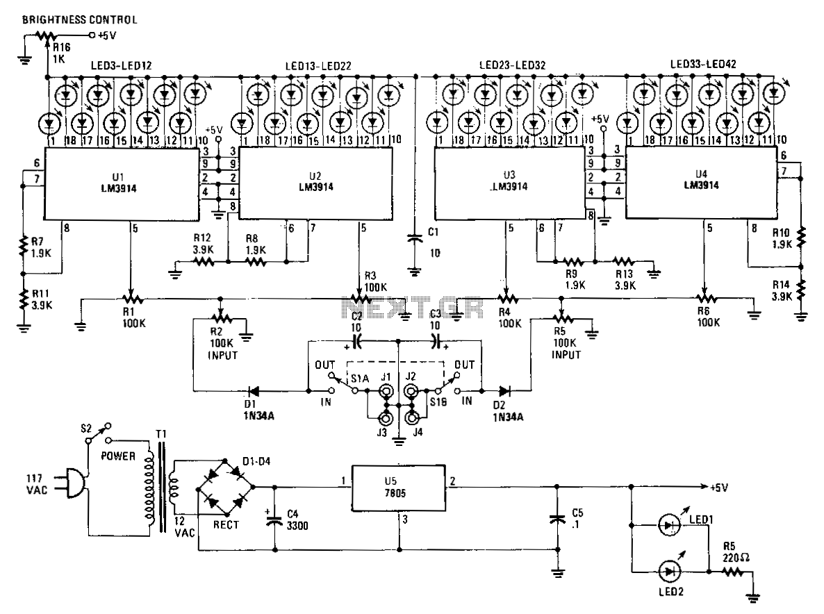
The Stereo Power Meter consists of two identical circuits and a power supply. Each circuit features two LM3914 display chips, which include 10 voltage comparators, a 10-step voltage divider, a reference voltage source, and a mode-select circuit that allows...

The frequency pulses originating from the mains supply are safely insulated by capacitors C1 and C2, along with inductor L1. These pulses are amplified by transistor Q1, while diodes D1 and D2 limit any peak voltages at the input....
This instrument is designed to help relieve nervous tension for individuals returning home from work with lingering stress. Known as the Galvanic Skin Response Monitor, it operates based on changes in skin resistance that correlate with emotional states. Increased...