
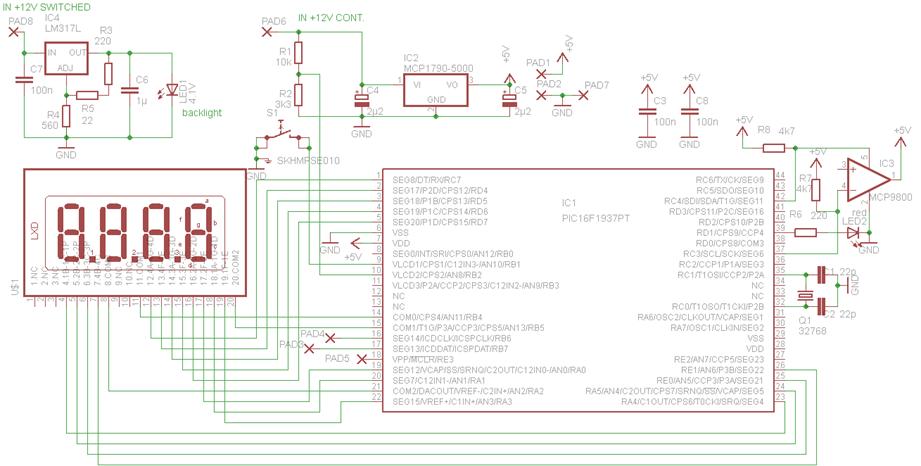
Case Modification - Stereo VU Meter

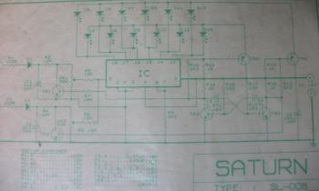
The stereo VU meter circuit using the LM3915/LM3916 ICs is a practical project that allows for visual representation of audio signal levels. The LM3916, in particular, is well-suited for this application due to its ability to drive multiple display elements simultaneously, providing an intuitive and engaging way to monitor audio levels.
To construct the circuit, begin by gathering the necessary components, which include the LM3916 IC, 10 LEDs (or an equivalent display type), a 2.2 µF tantalum capacitor (if required), resistors for current limiting, and a suitable power supply. The circuit operates by connecting the audio signal to the input pin of the LM3916, which processes the analog voltage levels and activates the corresponding number of LEDs based on the input signal strength.
When prototyping on a breadboard, it is essential to ensure that all connections are secure and that the power supply is correctly configured. The arrangement of the components can be customized to fit the desired aesthetic or functional requirements. Once the prototype is tested and verified, a permanent circuit layout can be designed, taking into consideration factors such as wire lengths and connector types. DUBOX connectors are particularly useful for making modular connections, allowing for easy adjustments or replacements of LEDs.
In summary, the LM3916-based stereo VU meter provides an excellent opportunity for both learning and practical application in electronics. With careful planning and execution, this project can yield a functional and visually appealing audio level indicator.This is a quick how-to guide for making a stereo VU meter using the LM3915/LM3916. The LM 3916 is an integrated circuit (IC) that takes analog voltage levels and drives 10 LEDs, LCDs, or vacuum fluorescent displays to represent digital voltage levels just like a VU meter. The 2. 2 uF Tantalum Capacitor is only needed if your wires from the IC to t he LEDs are longer than 6 inches. Although the specs for the LM3916 say you can use any voltage from 3 V to 20 V, I suggest using at least 12 V to power your circuit. So before soldering everything together, let`s just test the circuit on a protoboard. First let`s get everything ready. The following items are what we need for this project: After getting all the components ready, it is time to start prototyping.
First to be placed onto the protoboard is the most important piece, the LM3916 IC. Now it`s time to design the permanent circuit. Here is where you can get creative, you can arrange them the way you want them, and find creative ways to put it all together. Here is howI did mine. I used DUBOX connectors (those blue things you see in the picture). By using those connectors I could just use the wires you see in the next picture (hanging from the power supply) to change LED color or simply making longer or shorter wires to reach my LEDs.
🔗 External reference
Related Circuits
This device is designed to replace the original digital clock in a Fiat Ducato manufactured between 1992 and 1994. It is mounted above the inside rearview mirror. The original clock has limitations, including poor accuracy, a singular time display,...
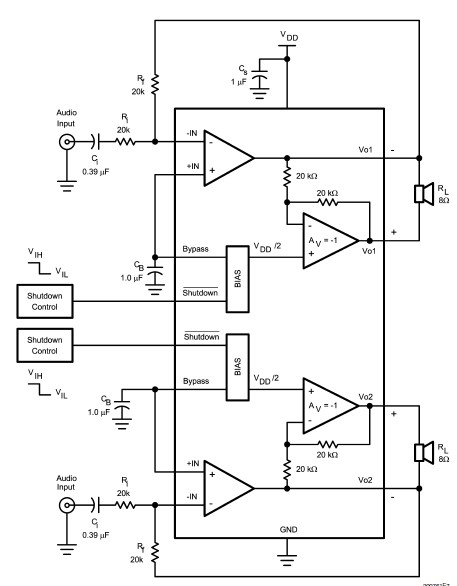
The LM4992 stereo audio power amplifier can be utilized to design a straightforward audio power amplifier project suitable for portable electronic devices. This amplifier circuit is capable of delivering 1 watt of continuous average power per channel to an...
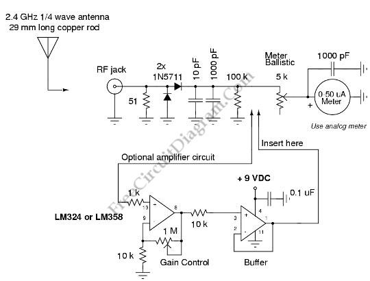
Field strength meters are essential tools for individuals working with radio transmitter electronics. The following is an example of a circuit that serves this purpose. A field strength meter circuit typically consists of several key components, including an antenna, a RF...
A circuit for measuring levels based on a typical application of National. A measurement circuit designed for level detection typically employs a combination of sensors and signal processing components to provide accurate readings. In this context, the circuit can utilize...
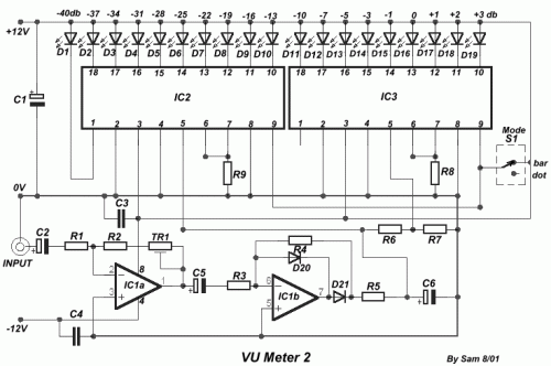
The following circuit is a six LED stereo VU display diagram that is constructed using the Dot/Bar Display Driver IC LM3915. This VU display should be connected before the amplifier module circuit. It can be connected at the pre-amp...
The layout of the PC board led to the decision to insert a stereo 3mm canceling type jack (5 pin) at the volume control chip inputs, which was mounted on the front panel. A suitable jack was not available...