
Simple flower circuit

The circuit operates by utilizing a series of resistors (Rp1 to Rp13) which are integral to both the keyboard input and the timing function of the oscillator. Each resistor is connected to a corresponding switch (S1 to S13), allowing for user interaction. When a switch is pressed, it activates the circuit, allowing current to flow from the +6 V power supply through the resistors and into capacitor C2. The capacitor is initially uncharged, presenting a voltage of zero across its terminals, which prevents the transistor VT1 from conducting.
As the capacitor begins to charge, the voltage across it gradually increases. In this state, the base of transistor VT2 receives a bias voltage through resistor R from the +6 V supply. Once the voltage at the base of VT2 reaches the necessary threshold, VT2 turns on, allowing current to flow from its collector to its emitter. This current then flows through the connected speaker, producing sound as a result of the voltage drop across the speaker.
The circuit effectively combines the functions of a keyboard interface with an oscillator, where user input directly influences the timing and output characteristics. The careful selection of resistors and capacitors dictates the charge time of C2, thus controlling the timing of the output signal. The interaction between the components creates a responsive electronic system that can generate audio signals based on user input, making it suitable for applications such as simple synthesizers or sound-generating devices.Circuit works: Rp1 ~ Rp13 scale resistance to the keyboard, but also the oscillator timing resistor, C2 is wide discharge capacitor, S1-S13, the key switch. Press S1 a S13 any one, such as pressing S1, the +6 V power supply by Rp1, C2 and S1 to charge electricity. By charging initial C2 terminal voltage is zero, so the VT1 can not be turned on. At this time +6 V power source via R to provide a base bias VT2, VT2 conduction current through the VT2 of c, e pole flows through the speakers, and produce a higher voltage drop across the speaker.
Related Circuits

The circuit illustrated in Figure 4 is an AC timing circuit designed to operate for 4 hours. It utilizes the BH4024, a 7-stage serial binary counter/divider, in conjunction with a 555 timer circuit. The circuit is activated by a...
The 8-pin 555 timer is one of the most versatile integrated circuits (ICs) available, utilized in numerous projects. With minimal external components, it can be employed to construct various circuits, many of which do not pertain to timing applications....
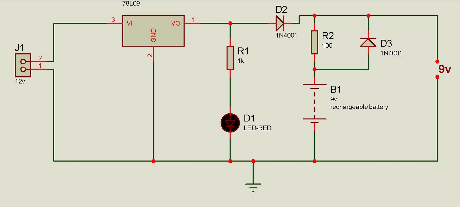
This battery backup circuit can be integrated into surveillance systems or alarm controls to provide power during mains power failures. The battery backup will immediately take over the load without any delay, and the circuit is simple to construct....
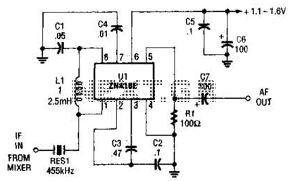
Up to 60 dB of gain at 455 kHz is available with the MC1350P. RES1 is a ceramic resonator, LC, or crystal filter. Keep the leads to pins 1, 2, 3, and 7 short. The MC1350P is a versatile integrated...
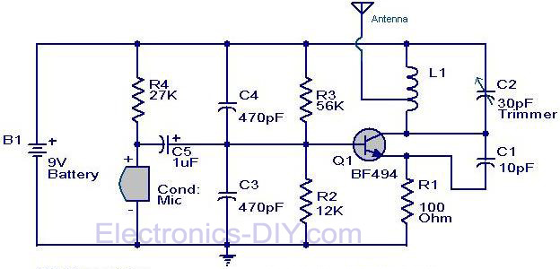
The circuit diagram of a simple FM transmitter utilizing a transistor is presented. While this design may not guarantee exceptional performance or range, it serves as a fundamental example. The circuit employs a general-purpose radio frequency transistor, the BF...
The core component of this circuit is the 555 timer IC. The alert sound does not stop immediately when the switch is activated; instead, it ceases automatically after a predetermined time period, which is set by the resistance of...