
FM Transmitter Circuit

The FM transmitter circuit operates by modulating the audio signal captured by the condenser microphone. The BF 494 transistor acts as the core component for both amplification and modulation. When sound waves strike the condenser microphone, it generates corresponding electrical signals, which vary in amplitude based on the sound intensity. These signals are then directed to the base of the BF 494, where they modulate the carrier frequency.
The capacitor C2 and inductor L1 form a tuned circuit that determines the operating frequency of the transmitter. The values of C2 and L1 can be adjusted to achieve the desired frequency range for transmission. This tuning capability allows for flexibility in selecting the operating frequency, which is essential for avoiding interference with other radio signals.
Powering the circuit with a 9V battery ensures sufficient voltage for the transistor to operate effectively while maintaining portability. It is essential to consider the placement of the transmitter to optimize range and performance, as the design is basic and may be limited by environmental factors.
Overall, this simple FM transmitter circuit serves as an educational tool for understanding the principles of modulation and amplification in radio frequency applications. Further enhancements can be made to improve performance, such as incorporating better components, shielding, or advanced modulation techniques.Here is the circuit diagram of the simple FM transmitter using a transistor. Great performance or range is not guaranteed here, because this is an elementary design. General purpose radio frequency transistor BF 494 (Q1) is used here for obtaining FM modulation. A condenser mic is used here to pickup the sound.The condenser mic converts the sound to electrical variations and this variations are fed to the base of Q1 , which performs the amplification as well as modulation.The capacitor C2 and L1 determines the frequency of transmission.The circuit can be powered from a 9V transistor radio battery. . 🔗 External reference
Related Circuits
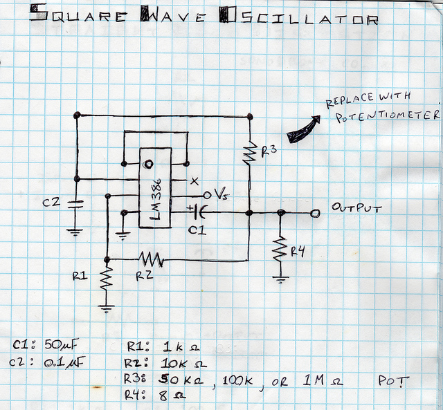
This is a square wave oscillator (digital, similar to 8-bit music). It is based on the LM386 amplifier integrated circuit, which is also the foundation for the mini guitar amplifier. The design includes a simple power switch connected to...
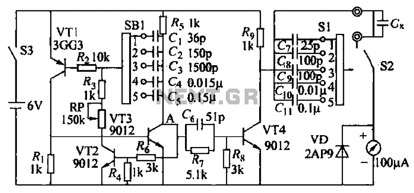
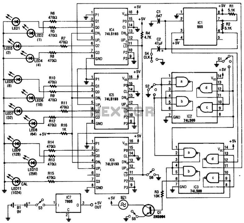
A capacitive measuring instrument is a direct reading device that measures the capacitance of a circuit. This instrument is capable of measuring capacitance values ranging from a few picofarads to 0.1 microfarads, with specific ranges of 25 pF, 100...
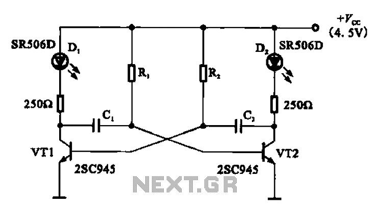
The multivibrator flashing light emitting diode (LED) display driver circuit can be utilized in toys, creating flashing effects in the eyes of animals or monsters. This circuit employs a multivibrator configuration, typically a 555 timer IC or a similar component,...
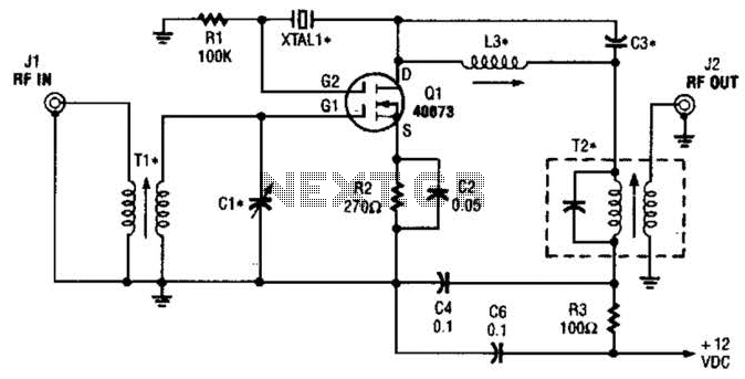
The second gate (G2) of a MOSFET can be utilized to integrate a crystal oscillator within the same stage as a frequency mixer. While this technique is common in tube technology, it is rarely implemented in dual-gate MOSFET circuits....
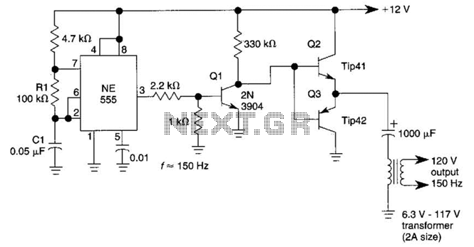
This DC-to-AC inverter utilizes the well-known 555 timer IC. A 555 oscillator circuit drives a buffer amplifier composed of transistors Q1, Q2, and Q3. The circuit operates at a frequency range of 150 to 160 Hz. Transformer T1 can...
A diode, such as the IN4148, has a typical temperature coefficient of -2 mV/°C at a 1 mA diode current. Transistors Q1 and Q2 form a constant current source. Diode D1 serves as the temperature sensor. Integrated circuits ICl-a...