
simple gauss detection switch

The ultra-sensitive gauss meter circuit is designed to detect magnetic fields with high sensitivity, utilizing a Hall effect sensor, which is a transducer that varies its output voltage in response to a magnetic field. The circuit typically includes a power supply section that provides the necessary voltage to the Hall sensor and other components. The Hall effect sensor generates a small voltage output, approximately 1.3mV per Gauss, which necessitates signal conditioning to amplify and filter this signal for practical use.
Signal conditioning may involve operational amplifiers to increase the output voltage, along with resistors and capacitors to form filters that eliminate noise and stabilize the output. This ensures that the small variations in voltage can be accurately interpreted by subsequent circuitry. A relay may be included in the design to act as a switch that activates or deactivates a load based on the detected magnetic field strength.
The choice of the Hall effect sensor integrated circuit is crucial, as its characteristics will determine the overall sensitivity and performance of the circuit. The circuit may be optimized by experimenting with the placement of the sensor within ferrite rings, which can enhance the magnetic field's strength at the sensor's location, thereby improving the sensitivity of the measurement.
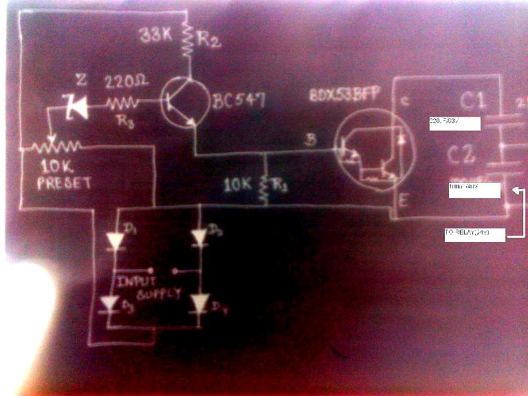
While magneto-resistive and magneto-inductive sensors are alternatives used in applications like compasses, they are often more complex and less accessible than Hall effect sensors. The simplicity of the Hall effect sensor circuit makes it an attractive option for various applications, provided that the limitations of the sensor are understood and addressed. Overall, this circuit can serve as a foundational design for those seeking to create a sensitive magnetic field detection system with minimal complexity.An ultra sensitive gauss meter circuit/schematic anywhere that constitutes a simple indicator No measurement. No scaling. No accuracy. Just hall device/ic on a board with power supply inputs, a bit of signal conditioning of maybe a dozen more parts, and a little relay.
If you look at the linear hall effect sensor it has an output of 1. 3mV per Gauss. That might be the limitation of hall effect sensors in general which might be where all your problems are coming from. It`s got me wondering why you never see hall effect sensors in things like compasses. You always see some kind of magneto-resistive or magneto-inductive sensor for those kinds of things, but those are neither straightforward to work with, nor easily available. Is it possible to implement so simple a circuit Or are these merely rough application examples Sensitivity would only depend on the IC that is inserted, no I`m in the process of testing that last one and it may work for me.
But I`ve asked a few questions about it here and elsewhere and don`t seem to be making any headway. The simpler the better. I just want an ultra sensitive switch circuit. I`m experimenting with placement of the sensor chip in various ferrite rings for better sensitivity. Here`s one example. 🔗 External reference
Related Circuits
A six-year-old child and an adult viewed a project on YouTube and captured an image of it using the print screen function to create a similar design. The project likely involves a basic electronic circuit that can be replicated easily,...
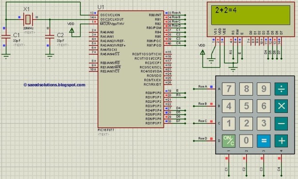
This PIC microcontroller tutorial provides a simple calculator implementation for the PIC16F877 microcontroller. This is a straightforward one-digit calculator. The PIC16F877 microcontroller is a versatile and widely used device in embedded systems, particularly for educational purposes and simple applications. The...
The post discusses a simple delay ON circuit that enables a connected load to be powered on with a predetermined delay after the power switch is activated. This circuit is applicable for any scenario that requires an initial delay...
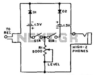
For use with headphones, this circuit sets the audio clipping level via a 5-kOhm potentiometer. This type of noise clipper is most effective for pulse-type noise with a low duty cycle, such as ignition noise. The resistor Rl establishes...
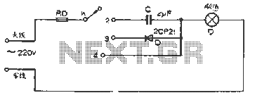
The figure illustrates a basic dimming lights circuit. The light intensity is controlled by a multi-speed control switch, designated as K. When switch K is set to position "1," the lights are turned off. In position "2," the light...
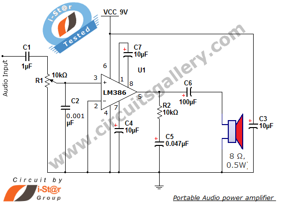
The i-St@r presents a simple mini audio amplifier circuit schematic utilizing the LM386 low voltage audio power amplifier IC. This circuit is designed to power medium-sized speakers from a music player that typically drives only earphones (LM386 headphone). The...