
Simple breadboard project with my 6 year old

The project likely involves a basic electronic circuit that can be replicated easily, providing an excellent opportunity for educational engagement between the adult and child. Such projects often focus on fundamental concepts in electronics, such as circuit design, component identification, and functionality.
To build a simple circuit based on typical YouTube projects, the schematic might include a power source, such as a battery, connected to a switch, a resistor, and an LED. The power source provides the necessary voltage to the circuit. The switch allows for the control of the circuit, enabling the user to turn the LED on and off. The resistor is used to limit the current flowing through the LED, preventing damage and ensuring proper operation.
For example, a common circuit might consist of a 9V battery connected to a SPST (Single Pole Single Throw) switch, which is then connected to a 220-ohm resistor in series with an LED. The LED will light up when the switch is closed, indicating that the circuit is complete.
This type of project serves as an introduction to basic electronics, allowing participants to learn about circuit components, their functions, and the principles of electricity in a hands-on manner. It fosters creativity and problem-solving skills while providing a platform for parents and children to collaborate and learn together.Hi all, My 6 year old son and I saw this on youtube I then pressed `print screen` from the video to cobble together this: .. 🔗 External reference
Related Circuits

This simple PC Smartcard reader was shown in Electronics Design magazine February 17, 1997 issue on page 172 in the ideas for design section. The circuit is designed by Jose Carlos Cossio and is based on simple smartcard reader...
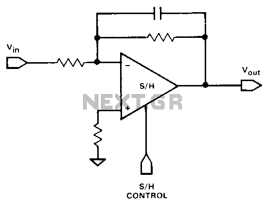
It is often necessary to filter a signal prior to sampling. This can be achieved using a single device. Any of the inverting or non-inverting filters that can be constructed with operational amplifiers (op-amps) may be utilized. However, it...
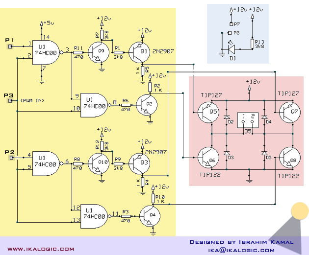
A relatively high-power H-bridge motor controller, which is a common method to control DC motors, utilizes inexpensive TIP transistors. A continuous current of 5 Amperes through an H-bridge module may not seem significant to some, depending on their background...
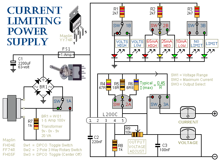
This is a 1-amp variable-voltage power supply unit (PSU) that adjusts the output voltage from approximately 3V to 24V. It features a current limiting option, which is particularly useful for initial power-ups or soak-testing equipment. SW3 acts as the...
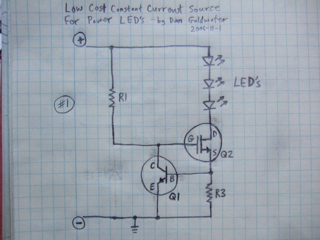
Here is a simple and inexpensive ($1) LED driver circuit. The circuit functions as a constant current source, ensuring that the LED maintains consistent brightness. The LED driver circuit is designed to provide a stable current to the LED, which...
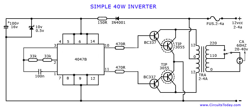
An article on how to create an inverter using a simple 40-watt inverter circuit diagram and schematics. This inverter converts 12 volts to 220 volts using the CD4047 integrated circuit. The described inverter circuit utilizes the CD4047 IC, which is...