
Simple dimming lights circuit diagram

This circuit employs a multi-speed control switch to adjust the brightness of a connected lamp through various operational modes. The switch K allows for four distinct settings, each altering the electrical characteristics supplied to the lamp.
In position "1," the circuit is open, effectively disconnecting the power supply from the lamp and resulting in no light output. This position is useful for completely turning off the lamp without needing to unplug it.
Position "2" introduces a capacitive coupling, which allows a small amount of current to pass through, creating a shimmering light effect. This is achieved by using a capacitor in series with the lamp, which charges and discharges, providing an alternating current (AC) effect that gives the lamp a flickering appearance. This setting can be particularly useful for decorative lighting or ambiance.
In position "3," the circuit employs a diode for half-wave rectification. The diode permits current to flow in only one direction, effectively reducing the power supplied to the lamp to about 50% of its rated value. This results in a dimmer light output, suitable for situations where less brightness is desired while still maintaining a steady light without flickering.
Position "4" connects the lamp directly to the power supply at its rated voltage, allowing it to operate at full brightness. This configuration is ideal for scenarios requiring maximum illumination, such as in workspaces or areas needing bright lighting.
Overall, this dimming circuit provides versatility in light control, allowing users to select the desired brightness level according to their needs. The use of capacitive coupling and rectification techniques ensures that different light effects can be achieved while maintaining simplicity in the circuit design.The figure is a simple dimming lights line, the light is adjusted by the multi-speed control switch K. When K to position "1" lights out; when K to position "2", the light shimmering through the capacitive connection; when K to position "3", the half-wave rectified by the diode power to the lamp power supply, lamp brightness about half the usual; when K to position "4", the lamp at rated voltage, the brightness of the brightest.
Related Circuits

This game can be played individually or with friends. The circuit consists of a timer IC, two decade counters, and a display driver paired with a 7-segment display. The objective of the game is straightforward: the player who reaches...
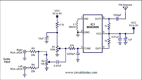
A simple single-chip FM transmitter circuit with a diagram and schematic using the IC MAX 2606, which is a high-performance voltage-controlled oscillator (VCO). The FM transmitter circuit utilizing the MAX 2606 is designed for efficient frequency modulation of audio signals....
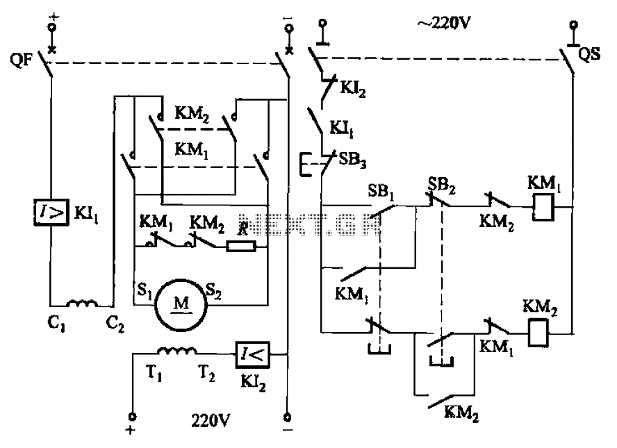
The circuit depicted in Figure 3-194 features a re-excitation type DC motor with six terminals: S1 and S2 for the armature windings; C1 and C2 for the series excitation (field) windings; and T1 and T2 for the shunt (field)...
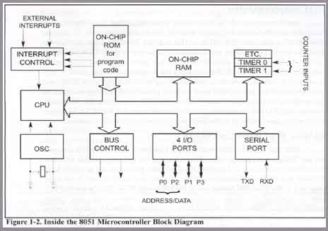
The 8051 microcontroller gained significant popularity after Intel permitted other manufacturers to produce and sell various versions of the 8051, provided these versions maintained code compatibility with the original 8051. The 8051 microcontroller is an 8-bit processor that was developed...
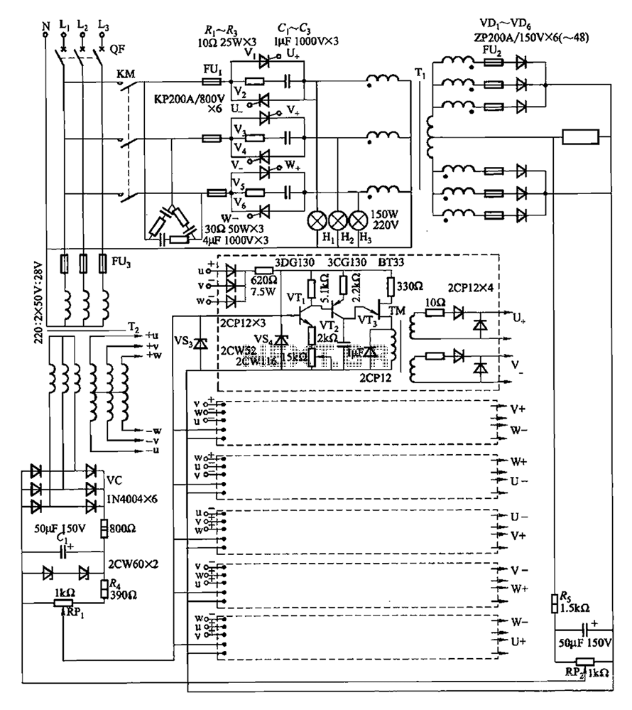
A three-phase thyristor power regulator circuit designed for plating applications, capable of handling currents from 1200A to 6000A at a voltage of 10V. The circuit comprises a main circuit, a trigger circuit, synchronous power components, and a voltage negative...
The Miniature DC Motor Speed Control circuit is designed to maintain a steady speed for micro motors, as illustrated in Figure 8-32. The circuit utilizes a voltage feedback mechanism suitable for applications such as tape recording machines that employ...