
Simple H-bridges Tutorial
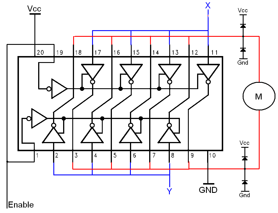
The H-bridge circuit consists of four switches, typically implemented using transistors or MOSFETs, arranged in a bridge configuration. The arrangement of these switches allows for the application of voltage across the motor terminals in either direction. By turning on specific switches, the current can be directed through the motor in one direction for forward motion, or in the opposite direction for reverse motion.
In its simplest form, the H-bridge can be controlled using two input signals. For example, when one input is high and the other is low, the motor will rotate in one direction. Conversely, if the inputs are reversed, the motor will rotate in the opposite direction. Additionally, if both inputs are low, the motor will stop, and if both inputs are high, it may lead to a short circuit condition, which should be avoided.
The H-bridge can also incorporate features such as pulse-width modulation (PWM) control to vary the speed of the motor. By adjusting the duty cycle of the PWM signal applied to the switches, the average voltage and current supplied to the motor can be controlled, allowing for precise speed regulation.
Protection mechanisms, such as diodes, are often included in the design to prevent back EMF generated by the motor from damaging the circuit components. These diodes, known as flyback diodes, provide a path for the inductive kickback when the motor is turned off, ensuring the longevity and reliability of the H-bridge circuit.
Overall, the H-bridge is an essential component in motor control applications, providing efficient and effective means to manage the operation of DC motors in various electronic systems.The H-bridge: The H-bridge is a commonly known, and commonly used way to drive a brushed DC motor. It allows for simple forward/reverse drive, .. 🔗 External reference
Related Circuits
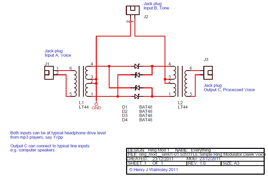
This is a simple ring modulator circuit designed to create interesting analog sound effects using two audio sources and an amplifier or recording device. With the widespread availability of MP3 players and powered computer speakers, building this circuit is...
AN6884 is a logarithmic scale LED bar display driver that accepts a wide range of supply voltages, from 3.5V to 16V. This device is designed for use in voltage unit (VU) bar displays. The AN6884 is specifically engineered to drive...
The frequency range is 100-108 MHz. The circuit is a mono circuit that accepts audio input from either a microphone or another source. The input impedance is 1 MΩ, with an input sensitivity of 5 mV and a maximum...
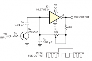
Audio frequency-shift keying (AFSK) is a modulation technique that represents digital data through variations in the frequency (pitch) of an audio tone, resulting in an encoded signal suitable for transmission via radio or telephone. Typically, the transmitted audio alternates...
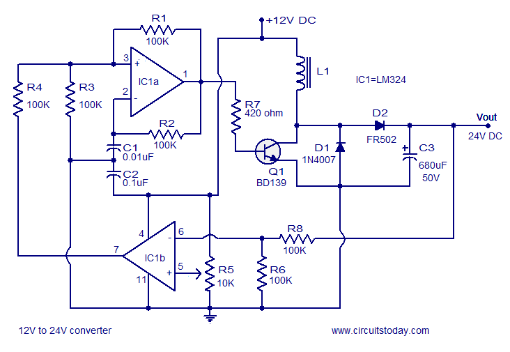
A simple 12V to 24V DC-DC converter circuit diagram built around the LM324. This boost converter schematic can provide up to 800mA output current and a steady 24V DC. The described circuit utilizes the LM324 operational amplifier as the core...
The bi-directional sequencer employs a 4-bit binary up/down counter (CD4516) along with two "1 of 8 line decoders" (74HC138 or 74HCT138) to create the well-known "Night Rider" display. A Schmitt Trigger oscillator generates the clock signal for the counter,...
Warning: include(partials/cookie-banner.php): Failed to open stream: Permission denied in /var/www/html/nextgr/view-circuit.php on line 713
Warning: include(): Failed opening 'partials/cookie-banner.php' for inclusion (include_path='.:/usr/share/php') in /var/www/html/nextgr/view-circuit.php on line 713