
Simple Indicator for Dynamic Limiter Schematic Diagram

The described indicator circuit serves as a crucial component in managing the dynamic limiter's performance by providing visual feedback through an array of 16 LEDs. Each LED corresponds to specific states of the limiter's operation, indicating varying levels of gain. The 4-to-16 decoder IC (4514) plays a vital role in translating the four-bit counter's output into a format suitable for LED activation. The design ensures that each LED is driven independently, preventing potential issues associated with using a common cathode resistor due to the higher supply voltage.
The arrangement of the LEDs allows for a clear visual representation of the limiter's status, facilitating real-time adjustments. The choice of colors for the LEDs enhances the user interface, allowing operators to quickly identify the operational state of the limiter. The use of red for the maximum gain indicator (D1) and green for the minimum gain indicator (D16) provides an intuitive understanding of the gain range, while yellow LEDs indicate intermediate levels.
Connecting the indicator circuit to the limiter's output via the K5 connector ensures seamless integration, allowing for straightforward monitoring and adjustment of the limiter's performance. The circuit's design accommodates various input sources, making it versatile for different applications. The feedback mechanism provided by the LEDs enables operators to fine-tune the potentiometer P1 effectively. By adjusting P1, operators can ensure that the limiter operates within the desired parameters, preventing distortion and maintaining signal integrity across different input levels.
In summary, this indicator circuit is an essential tool for optimizing the performance of the dynamic limiter, providing clear visual feedback and facilitating precise adjustments to maintain optimal signal levels.The indicator described here is specifically designed for adjusting the dynamic limiter described elsewhere in this edition and checking whether the maximum level of the reference voltage (P1) needs to be modified. Her e we use a 4 -to -16 decoder IC (type 4514) to monitor the state of the four-bit up/down counter in the limiter circuit.
This IC c an be powered from the ±8 V supply voltages of the limiter. The limiter board has a 6-way connector (K5) that provides access to the four counter outputs and the sup-ply voltages. Connector K1 of the indicator circuit can be connected to K5 on the limiter board. One output of the 4514 goes high for each unique 4-bit combination on its inputs, while the other outputs remain logic Low.
A separate current-limiting resistor is connected in series with each LED. It was not possible to use a common cathode resistor here because most LEDs have a maximum reverse blocking voltage of only 5 V, while the supply voltage here (16 V) is a good deal higher. The 16 LEDs ar ranged in a r ow pr ov ide a fluid` indication of the control process. You can enhance the display by using different colours for the first and last LEDs, such as red for D1 (maximum gain) and green for D16 (minimum gain), with yellow for the rest of the LEDs.
While observing signals from various sources (TV set, DVD, media player, etc. ), you can easily use the 16 LEDS to monitor the behaviour of the limiter and adjust the setting of potentiometer P1 in the limiter circuit. It must be set such that D16 only lights up at the maximum signal level. If this is not possible and D16 remains lit a good deal of the time regardless of the position of P1, it will be necessar y to increase the value of P1.
Of course, it is also poss-ible to adjust P1 so the strongest signal source extends slightly above the control range of the limiter. 🔗 External reference
Related Circuits
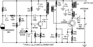
Clearly indicate on the circuit diagram each type and size of the components. There is a need for assistance in designing a low power FM transmitter circuit, specifically using the BA1404 FM transmitter with a center frequency of 79W...
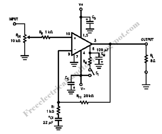
These accessories are low-cost, high-speed, bifet-input operational amplifiers utilizing internally compensated voltage (BI-FET II technology). They require low supply voltages while offering a wide gain bandwidth product and fast slew rate. Additionally, well-matched high voltage JFET input devices accommodate...
This is a design circuit for a simple function generator. Built around a single 8038 waveform generator IC, this circuit produces sine, square, or triangle waves from 20Hz to 200kHz in four switched ranges. There are both high and...
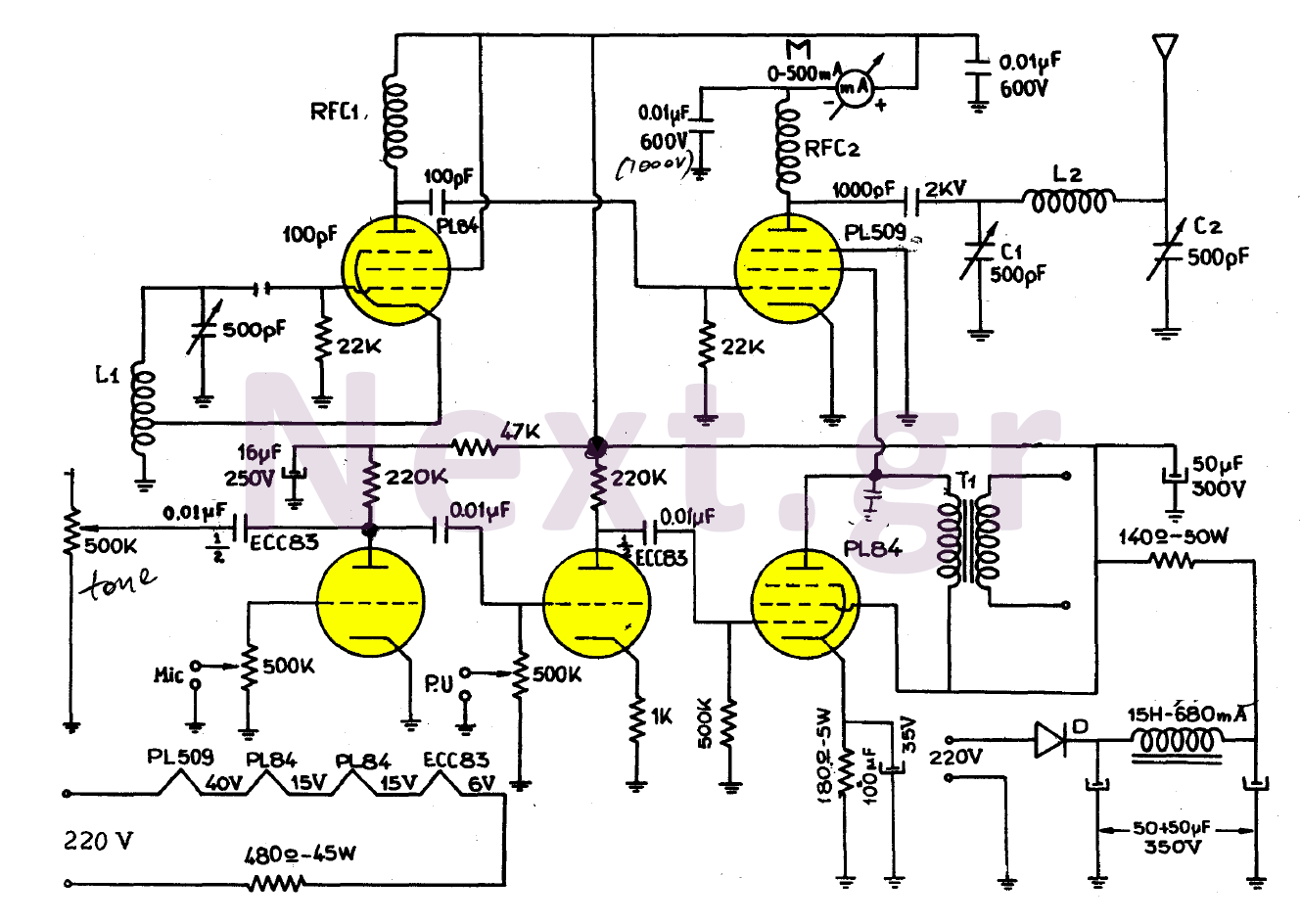
The simplicity of this transmitter, combined with its high performance, makes it particularly interesting. It has an output power of approximately 30 W, and under normal conditions, with the appropriate antenna and handling, it can achieve a range of...
Toyota MR2 Exterior Lights Wiring Diagram Manual PDF Download. The Toyota MR2 Exterior Lights Wiring Diagram Manual provides a comprehensive guide for understanding the wiring configurations associated with the exterior lighting system of the Toyota MR2 model. This manual is...
Charging the battery in a slow manner (using a low charging current over an extended period) is the most economical and safest method. The design of the trickle charger should focus on two key points: firstly, the use of...