
Simple Intercom circuit

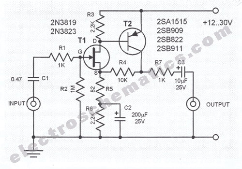
The described circuit functions as a basic intercom system utilizing a 3-stage RC (resistor-capacitor) coupled amplifier configuration. The primary operation begins with the activation of switch S2, which initiates the amplifier circuit built around transistors T1 and T2. This arrangement is designed to operate as an asymmetrical astable multivibrator, a circuit configuration that generates a continuous square wave output. The frequency of this output can be adjusted by varying the values of the resistors and capacitors in the circuit, allowing for customization of the ring signal's characteristics.
Transistor T3 serves a crucial role in the circuit, as it amplifies the generated ring signals to a level sufficient to drive a speaker, typically an earpiece in this application. The low current consumption of 10 to 15 mA makes the system efficient, allowing the use of a 9-volt PP3 battery, which can provide extended operational life due to the minimal power requirements.
To create a two-way intercom system, two identical units are necessary. The design allows for the output from one amplifier unit to be routed to the speaker of the other unit, effectively enabling bidirectional communication. For a single-battery setup, the corresponding power and ground terminals of both units should be interconnected, simplifying the power supply arrangement.
The entire system, including components such as the microphone and earpiece, can be conveniently housed within the plastic casing of a cellphone toy. This design choice not only provides a compact and portable form factor but also utilizes readily available materials, making the project accessible for hobbyists and engineers alike. The suggested cellphone cabinet serves as an effective enclosure for the intercom circuitry, ensuring protection and ease of use.The circuit comprises a 3-stage resistor-capacitor coupled amplifier. When ring button S2 is pressed, the amplifier circuit formed around transistors T1 and T2 gets converted into an asymmetrical astable multivib-rator generating ring signals. These ring signals are amplified by transistor T3 to drive the speaker of earpiece. Current consumption of this intercom is 10 to 15 mA only. Thus a 9-volt PP3 battery would have a long life, when used in this circuit. For making a two-way intercom, two identical units, as shown in figure, are required to be used. Output of one amplifier unit goes to speaker of the other unit, and vice versa. For single-battery operation, join corresponding supply and ground terminals of both the units together. The complete circuit, along with microphone and earpiece etc, can be housed inside the plastic body of a cellphone toy, which is easily available in the market.
Suggested cellphone cabinet is shown. 🔗 External reference
Related Circuits
This microphone preamplifier utilizes the low-noise integrated circuit uA739. The circuit serves as an example of an effective preamplifier design for dynamic microphones. The integrated circuit contains two identical preamplifier circuits, with the second preamp functioning in the same...
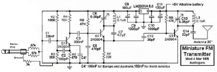
This small FM transmitter can be modified to replace the microphone with an audio jack, allowing it to connect to an MP3 player for audio playback through car audio systems. The design is straightforward and intended for a short...
The electric car remote control circuit diagram enables the model car to move forward and backward, as well as turn left and right. It is simple and easy to operate. The radio remote control receiver demodulation circuit utilizes TWH9238...
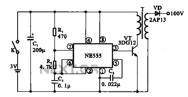
This circuit illustrates a simple boost converter, which is powered by an oscillating signal generated by the NE555 timer. The signal is amplified through a VT transistor to drive a booster transformer. This step-up transformer increases the oscillating signal,...
The ultrasonic drilling machine is essential machinery in the dairy industry for processing jewelry, primarily for natural stones, crystal agate, jade, and glass products. This machine is particularly effective for high-hardness materials, enabling both drilling and engraving. The following...
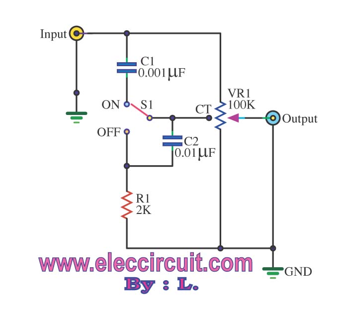
The passive tone control circuit is designed to adjust the bass without expansion, utilizing resistors (R) and capacitors (C). It functions as a frequency filter and is easy to construct, requiring no external power supply. This circuit can be...