
Simple LED Tester

A multimeter is an essential instrument in electronics, used for measuring voltage, current, and resistance. Its design typically includes a digital or analog display, a rotary switch for selecting measurement modes, and input jacks for connecting test leads. The device can measure direct current (DC) and alternating current (AC) voltage, making it versatile for various applications.
In a typical multimeter circuit, the core components include an analog-to-digital converter (ADC) for digital displays, operational amplifiers for signal conditioning, and resistors for current measurement. The rotary switch allows users to select different measurement functions, which connects the appropriate circuitry to the display. The test leads, usually color-coded red for positive and black for negative, connect to the circuit under test.
For enhanced functionality, some multimeters incorporate features such as continuity testing, diode testing, and temperature measurement. These additional capabilities are achieved through specialized circuitry and sensors. The inclusion of a microcontroller can further expand the device's features, allowing for data logging and advanced computations.
The simplicity of a multimeter belies its utility in both professional and hobbyist applications. It is a fundamental tool for troubleshooting electrical issues, verifying circuit functionality, and conducting experiments in electronics.Do not let its extreme simplicity deceive you — this thing is useful! I have made many over the years and have even given some away as gifts. Yes multimete.. 🔗 External reference
Related Circuits
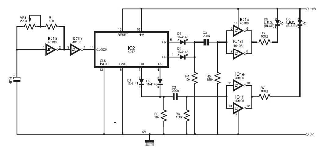
This circuit simulates the flashing lights of a police car, similar to those seen on British police vehicles. The operational amplifier IC1a functions as a square wave oscillator, with an adjustable frequency controlled by the variable resistor VR1 to...
.jpg)
This article contains an assembly language listing that requires MAC/65 or the Atari Assembler Editor, along with access to an EPROM burner. The previous three installments were published in the January, February, and March 1985 issues of Antic. This...
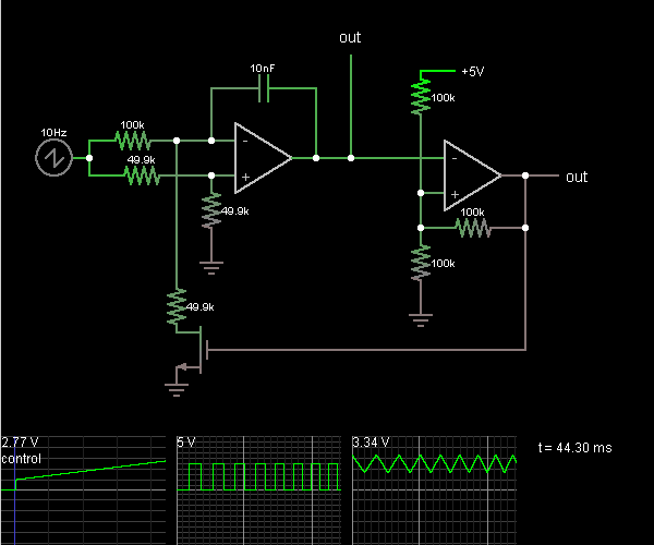
This circuit is a voltage-controlled oscillator, which is an oscillator whose frequency is determined by a control voltage. A 10 Hz sawtooth oscillator provides the control voltage in this case; this causes the frequency to rise slowly until it...

There have described the involvement benefited LM3909 circuit, which is quite expensive. That's why I prefer to use a much cheaper known timer 555th. Involvement of the tree is a very simple scheme is to figure 2. It is...
This is a novel flasher circuit using a single driver transistor that takes its flash-rate from a flashing LED. The flasher in the photo is 3mm. An ordinary LED will not work. The flash rate cannot be altered by...
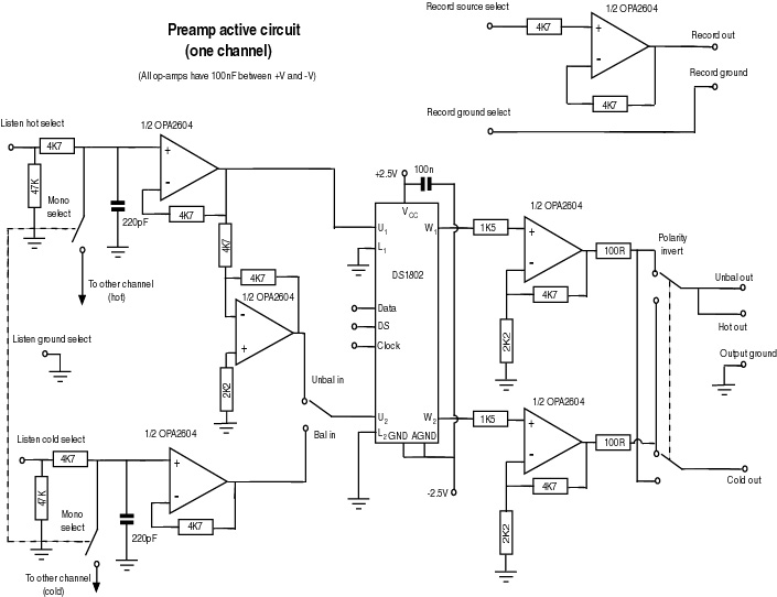
This document serves as a compilation of design notes, providing practical details as construction progresses, along with some photographs that will be included in due course. Currently, it functions as a progress report, blending immediate plans with actual construction,...