
Simple LF converter

The described converter is designed to facilitate the reception of signals within a specified frequency range, specifically from 25 kHz to 500 kHz. The use of a short coaxial cable is crucial for minimizing signal loss and ensuring optimal performance when connecting the converter to the receiver's antenna input.
To effectively utilize the converter, the user must set the receiver to a frequency of 3 MHz. This initial setting allows the user to calibrate the receiver by adjusting for the strongest signal from a crystal calibrator, which serves as a reference point. Following this calibration, the user can then incrementally tune the receiver to higher frequencies, which correspond to specific lower frequency ranges. For instance, maintaining the receiver at 3 MHz aligns with a 200 kHz output, while further adjustments will yield 300 kHz and 500 kHz outputs. Notably, tuning the receiver to 4 MHz also provides a 500 kHz output, showcasing the versatility of the converter in accessing multiple frequency ranges with a single tuning adjustment.
This operational method highlights the importance of precise tuning and calibration in achieving effective signal reception across the defined frequency spectrum. The converter's design and recommended operational procedures ensure that users can efficiently access and utilize the lower frequency ranges for various applications, such as communication or signal analysis.This converter allows coverage from 25 kHz up to 500 kHz. Use short coax from the converter to receiver antenna input Tune the receiver to 3 MHz, peak for loudest crystal calibrator and tune your receiver higher in frequency to 3 MHz and you"re tuning the 100 kHz range. 3 MHz puts you at 200 kHz, 3 MHz equals 300 kHz, 3 MHz yields 500 kHz, and 4 MHz gives you 500 kHz.
Related Circuits
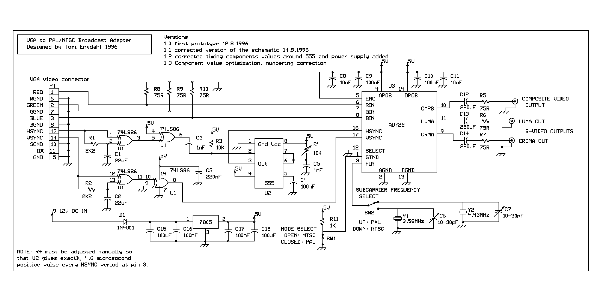
The circuit needs that the VGA card sends out the video signal in the RGB format compatible with PAL or NTSC standard video timings. This is accomplished with the right VGA to TV driver. More: This circuit is based...
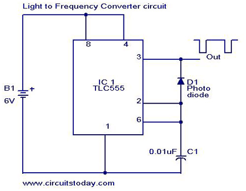
A simple light-to-frequency converter circuit with a diagram and schematic. It is used as a light intensity measurement circuit. The design utilizes the TLC555, a CMOS version of the NE555 timer IC. The light-to-frequency converter circuit is designed to convert...
Logic-1 and logic-0 represent the states of digital signals, where logic-1 corresponds to a high voltage close to Vcc, and logic-0 corresponds to a voltage near neutral or ground. Logic-0 cannot be transformed into logic-1, while logic-1 can revert...
Most small internal combustion engines commonly used in the model-building world utilize glow plugs for starting. Unfortunately, glow plugs have an operating... Glow plugs are essential components in many small internal combustion engines, particularly in the context of model building....
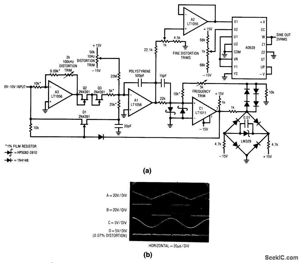
Most of the voltage-to-frequency (V/F) converters discussed in this chapter generate pulse or square-wave outputs. However, many applications, such as audio processing, filtering, or automatic equipment testing, necessitate a sine-wave output, which is produced by this particular circuit. The...
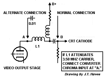
The D 101-2 depends on the television to supply a wide bandwidth video signal. Most black-and-white TVs from 1954 onward contain narrowband intermediate frequency (IF) strips or low-pass filters. A wide passband is a disadvantage because it picks up...