
Simple Low-Pass (Lp) Active Filter For 1Khz Circuit
 Active Filter For 1Khz")
The described circuit functions as a low-pass filter, where the resistor (R) and capacitor (C) form the essential RC network. The voltage follower, implemented using an operational amplifier (op-amp), serves to buffer the output, ensuring that the filter does not load down the previous stage and maintains signal integrity.
The cutoff frequency, defined as the frequency at which the output power drops to half its maximum value, is determined by the RC time constant. Specifically, the formula for the cutoff frequency (fc) can be expressed as fc = 1/(2πRC). Here, RXCV represents the product of resistance (R) and capacitance (C) in the circuit. The term 6.28 in the description is effectively 2π, indicating the relationship between frequency and the RC time constant.
As the frequency increases beyond the cutoff, the output voltage decreases at a rate of 6 dB per octave, which corresponds to a factor of 10^(−6/20) for every doubling of frequency. This attenuation is characteristic of first-order low-pass filters and is crucial in applications where it is necessary to eliminate high-frequency noise while preserving lower frequency signals.
In practical applications, this filter design is useful in audio processing, signal conditioning, and various electronic systems where frequency selection is required. The voltage follower ensures that the filter can drive subsequent stages without distortion or signal degradation, making it a versatile component in the design of electronic circuits. This simple filter uses an RC section for a filter element, with a voltage follower for other frequencies /3 dB = 1/6.28 RXCV Response drops 6 dB/octave above/3 dB.
Related Circuits
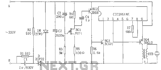
The rice cooker notification circuit operates as follows: When the rice cooker is in operation, both terminals A and B have a voltage of 0, meaning the entire circuit remains inactive. In the event that the rice cooker runs...
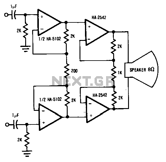
This circuit demonstrates a method to enhance the power capability of a drive system for audio speakers. Two HA-2542 amplifiers are utilized to operate on half cycles only, significantly increasing their power handling capacity. Bridging the speaker, as illustrated,...
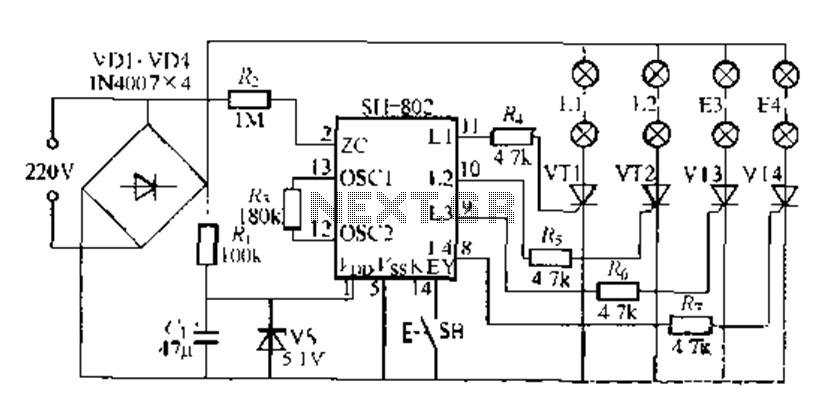
A digital integrated circuit simplifies the response process significantly. The diagram illustrates a circuit comprising four responder groups. The digital integrated circuit described serves as a crucial component in various electronic systems, primarily focusing on enhancing response efficiency. It comprises...
This is a circuit which I originally included in my book, 22 Tested Transistor Projects, published by Babani Press in 1976 (ISBN 0 900162 63 S). It is one I had great fun with. It uses the PUT Complimentary...
A relatively simple circuit for controlling a stair walkway light with a delay feature. The circuit has a drawback in that the voice activation is somewhat less sensitive, making it sometimes difficult to trigger with general conversation. However, it...
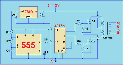
This project involves a simple 12V to 220V modified sine-wave inverter utilizing a 555 timer IC and a CD4017 decade counter. The inverter is capable of delivering 300W of continuous power and approximately 500W of maximum power output for...