
traffic light circuit diagram

The traffic light system controller is designed to manage the flow of vehicles and pedestrians at an intersection efficiently. The architecture separates the controller from the controlled circuitry, allowing for modular design and flexibility in programming. The controller interprets input signals, which are active high, and generates output signals that dictate the state of the traffic lights. The design incorporates a timing mechanism that ensures traffic lights change states at predetermined intervals, enhancing safety and efficiency.
In the VHDL implementation, the controller's functionality is expressed through a series of state transitions, as outlined in the ASM chart. Each state corresponds to a specific configuration of the traffic lights, ensuring that vehicles and pedestrians receive appropriate signals based on real-time traffic conditions. The timing intervals are critical, as they determine how long each light remains active, thus influencing traffic flow and pedestrian safety.
The simulation process within the MAX PLUS environment allows for thorough testing of the design before deployment. It enables designers to verify that all components interact correctly and that the system adheres to the specified timing and logic requirements. Any errors detected during simulation must be addressed, ensuring that the final design is robust and reliable.
Overall, the integration of EDA technology and VHDL in the design of traffic light systems represents a significant advancement in electronic engineering, facilitating the creation of sophisticated control systems that are both efficient and adaptable to varying traffic conditions.The design of the current application of the wider selection of VHDL hardware description language to realize the intersection traffic light system controller hardware circuit description, in the Altera`s MAX PLUS EDA software platform environment through the compilation, simulation, and ed to the CPLD production of the device is programmed to ach ieve the traffic light system control process. Keywords: EDA; VHDL; controller; CPLD Introduction EDA technology is used in electronic product design, more advanced technology, can replace the design of electronic systems designers to complete most of the work, and can be modified directly from the program and system errors function without the need for hardware support, not only shorten the development cycle, but also significant cost savings by the electronic engineers of all ages. To achieve control of intersection traffic signal systems are many ways you can use the standard logic devices, programmable logic controller PLC, SCM and other programs to achieve.
However, the function of these control methods are required to modify and debug hardware support, to a certain extent, an increase of functional changes and system debugging difficulties. Therefore, the use of EDA in the design of technology, applications are now widely used in the VHDL hardware description language to realize the design of traffic signal system controller, using MAXPLUS comprehensive integrated development environment, simulation, and to the CPL D programmable logic device, complete Control of the system.
Traffic light system controller design requirements junction traffic light control system and other control systems, controllers and the controlled circuit is divided into two parts. Controller so that the whole system works by setting alternate command vehicles and pedestrians, traffic, and receiving controlled part of the feedback signal and determine the direction of state transition and output signals to control the whole system works.
Intersection traffic operation in accordance with the actual situation, in this system, set the system works as follows. Intersection traffic light control system of traffic lights the road things R (red), Y (yellow), G (green); things safe passage pedestrian lights: RXR (red), RXG (green).
North-south road with traffic lights: r1 (red), y1 (yellow), g1 (green); safe passage north-south pedestrian lights: rxr1 (red), rxg1 (green), all lights are lit high. Set the passage of time and 5s 15s conversion time of change model timing, the decision by the preset input is an integer cnt die 15 or die 5, the input logic is used to determine the count to cx 4 to 14, or cleared when cleared.
Clk is the second externally supplied reference pulse signal. x0, x1, x2, x3 is output by the controller, said four binary count of time. Figure 1 is a symbolic diagram of the system controller. Controller * controller ASM programming plans based on system design requirements, get the controller ASM chart shown in Figure 2. Here, all input signals are active high. The ASM chart reflects the different states of traffic signal systems and the duration of the conversion process.
* VHDL programming the controller of the system according to the ASM chart, combined with the design requirements of each module using VHDL programming language, and finally form a top-level file, MAX PLUS compilation and simulation environment to check the programmed is operating correctly. If an error occurs, you need to be modified until it get approved. It should be noted that, during the compilation process, the first program from the ground up, all the underlying programs are correct, can begin to compile top-level program.
This is because the top-level program is a summary of the underlying process, which is the underlying process linking the various modules, each module is equivalent to the function of gathering together to achieve the overall system con 🔗 External reference
Related Circuits
A simple function generator that produces a specific frequency. While awaiting the arrival of the AD9832 chip, a basic version of a Direct Digital Synthesis (DDS) synthesizer was developed using only the AT2313 microcontroller and a resistor network. This...
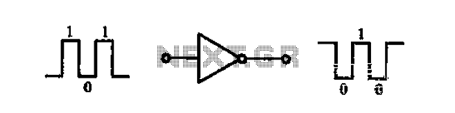
A common-emitter transistor amplifier produces an output signal that is 180 degrees out of phase with the input signal, commonly referred to as an inverting amplifier. When the electrical path for amplifying the pulse signal is activated, this circuit...
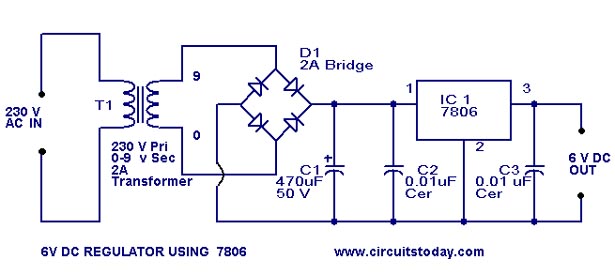
A simple 6-volt DC regulator circuit with a diagram and schematic using the 7806 IC, a positive voltage regulator. It serves as an elementary 6-volt, 1-ampere power supply circuit. The 7806 voltage regulator is a widely used integrated circuit that...

The schematic includes programmable AVRs. For other members of the AVR family or additional programmable ICs compatible with Ponyprog, there is a J1 connector (CON10) that facilitates hardware expansion of the programmer. Additional information about compatible ICs can be...
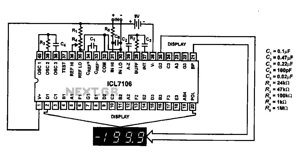
This circuit utilizes the ICL7106 / ICL7107 chip to drive a liquid crystal display (LCD). In this configuration, the ICL7106 / ICL7107 functions as a signal measurement and analog-to-digital (A/D) converter. It detects an analog input signal, amplifies it,...
The circuit consists of a light metering circuit and a flash circuit, as illustrated in the accompanying image. It is designed for use with integrated cameras such as POPTICS, Franka X-500, and WIZEN-860S. The circuit includes the following components:...