
Simple Microphone Preamp

The described preamplifier circuit is designed to amplify low-level audio signals generated by a small dynamic microphone. The microphone serves as the input transducer, converting sound waves into electrical signals. The gate of Q1, which is typically a field-effect transistor (FET), is the primary amplification component in this configuration.
R1, the load resistor, plays a crucial role in setting the operating point of the transistor and determining the gain of the amplifier. The value of R1 can be selected based on the desired output characteristics and the specific microphone being used. The audio signal is extracted from the negative terminal of capacitor C1, which serves to block any DC component from the output, allowing only the AC audio signal to pass through to subsequent stages of processing or amplification.
The output voltage range of 10 to 100 mVpp indicates the circuit's sensitivity to variations in microphone performance, as different microphones will produce varying output levels based on their design and acoustic environment. This preamp circuit is suitable for applications where low-level audio signals need to be amplified for further processing, such as in audio recording systems, public address systems, or any application requiring sound capture and amplification.
Overall, this preamplifier design emphasizes simplicity and efficiency, making it an effective choice for integrating small dynamic microphones into larger audio systems. Proper attention to component selection and circuit layout will enhance performance and reliability in practical applications. This preamp uses a small dynamic microphone coupled to the gate of Ql. R1 is a load resistor. Audio is taken out b etween the negative side of CI and ground. Output will be between 10 and 100 mVpp, depending on the microphone.
Related Circuits
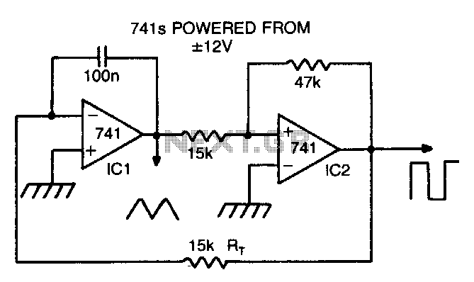
By making Rt variable, it is possible to alter the operating frequency over a 100 to 1 range. The versatile triangle/square wave oscillator has a possible frequency range of 0 Hz to 100 kHz. The described circuit features a variable...
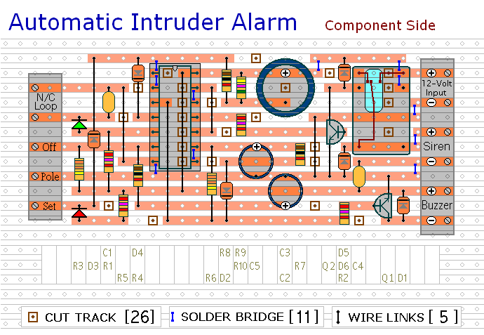
This circuit includes automatic exit and entry delays, a timed bell cut-off, and a system reset feature. It is designed to work with standard normally-closed input devices such as magnetic reed contacts, micro switches, foil tape, and passive infrared...
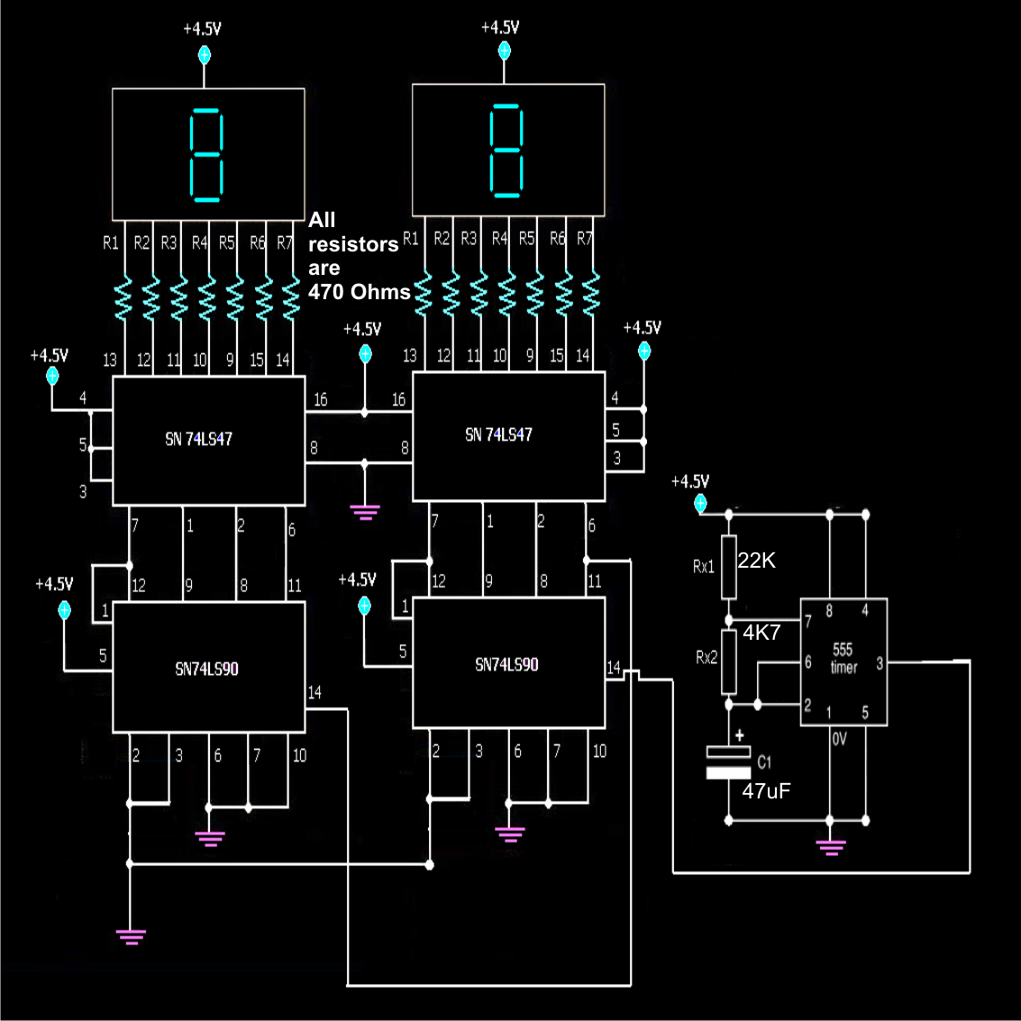
A simple frequency counter circuit can be easily constructed by any electronics enthusiast for its intended purpose. The circuit diagram was provided by Mr. Kapital through an order on Fiverr. The functioning of the circuit involves generating positive voltage...
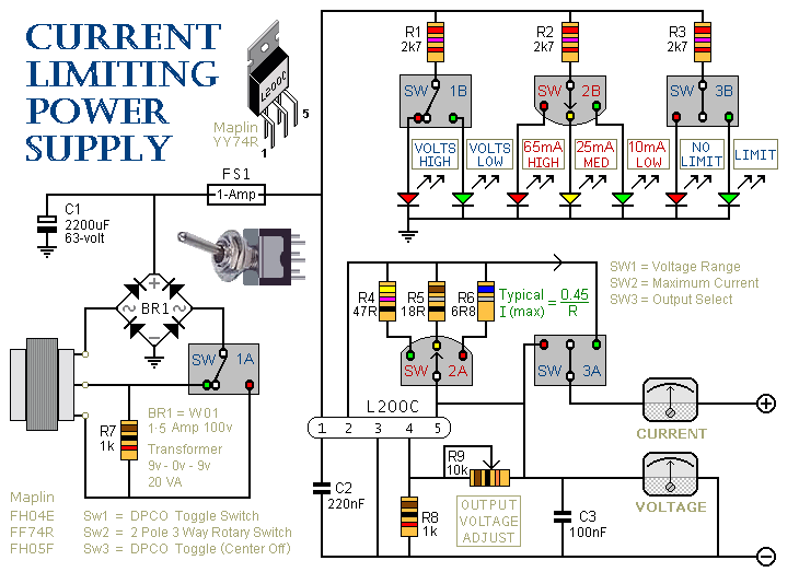
This is a 1-amp variable-voltage power supply unit (PSU) that adjusts the output voltage from approximately 3V to 24V. It features a current limiting option, which is particularly useful for initial power-ups or soak-testing equipment. SW3 acts as the...
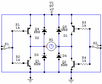
You have 4 transistors, wired as ON OFF switches. Two signal lines allow you to run the motor in one direction, when reversed, the motor runs in the other direction. It's very straightforward to use and build, but be...
The circuit was designed to create a line preamplifier using double triode tubes. It consists of three parts, including the main preamplifier. The line preamplifier circuit utilizing double triode tubes is structured to enhance audio signals by amplifying low-level signals...