
simpler cmos single zone alarm

The described circuit operates by managing the timing and control of various entry and exit points in a security system. The automatic entry and exit delays are essential for providing users sufficient time to enter or exit the monitored area without triggering an alarm. The timed bell cut-off feature allows for a defined duration during which an alert sound is emitted, ensuring that alarms do not sound indefinitely, which could lead to unnecessary disturbances.
The system reset function is crucial for reinitializing the circuit after an alarm has been triggered or after a user has entered or exited the premises. This ensures that the system is ready for the next cycle of use. The inclusion of normally-closed input devices ensures that the circuit remains in a secure state until a breach is detected, at which point the circuit can trigger an alarm or alert system.
For installations requiring flexibility, the option to modify the circuit to accept normally-open triggers allows for the use of additional devices, expanding the circuit's functionality. This adaptability makes the circuit suitable for a variety of applications, from residential security systems to commercial entry control systems.
In terms of implementation, the circuit would typically include a microcontroller or timer IC to manage the delays and reset functions, alongside input terminals for connecting the various sensors. Output terminals would connect to alarm systems or notification devices, ensuring that all components work cohesively to provide effective security monitoring. Proper attention to component selection and circuit design will ensure reliability and responsiveness in real-world applications.This circuit features automatic Exit/Entry delays, timed Bell Cut-off and System Reset. It will accommodate the usual normally-closed input devices (Magnetic Reed contacts, Micro Switches, Foil Tape and PIRs). And - with a simple modification - a normally-open trigger may be added.. 🔗 External reference
Related Circuits
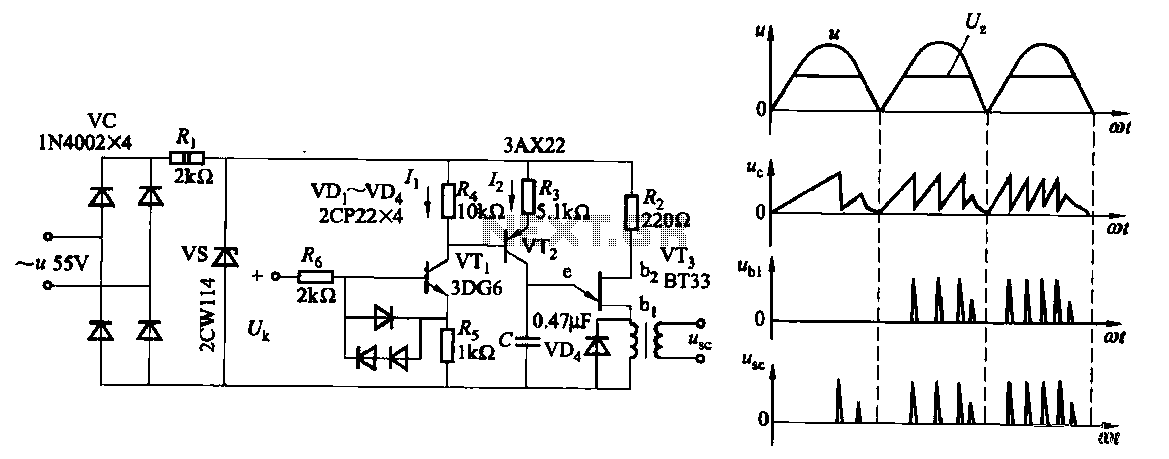
Due to the increased level of the transistor amplifier circuit, the control circuit's performance in Figure 16-6 is more sensitive and can accept input control signals superimposed on others (such as voltage, current, and speed feedback signals) to meet...
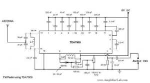
The following circuit illustrates a Single Chip FM Radio Circuit. This circuit is based on the IC TDA 7000 or TDA 7400. Features include a low-cost FM radio circuit. The Single Chip FM Radio Circuit utilizing the TDA 7000 or...
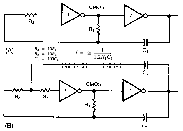
The common clock oscillator illustrated in Fig. 68-19A has two minor issues: it may not oscillate if the transition regions of its two gates differ. If it does oscillate, it might occasionally operate at a slightly lower frequency than...
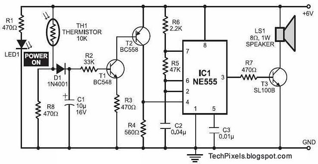
The following circuit illustrates a fire alarm circuit diagram utilizing the NE555 integrated circuit (IC). Features include functioning as a heat sensor and incorporating a 10 kilo-ohm resistor. The fire alarm circuit based on the NE555 IC is designed to...

This is a simple digital counter circuit utilizing the IC 4029 to process binary data, which is then sent to the IC 4513, a driver IC for a 7-segment display to show the output. The digital counter circuit is designed...

This is a simple SCR-based burglar alarm circuit. Its features include automatic exit and entry delays, along with a timed bell cut-off and reset. The basic alarm has a single zone, which is adequate for many situations. However, the...