
Simple Surround Sound Decoder

The simple surround sound decoder utilizes the Hafler principle to create an immersive audio experience by processing stereo signals to produce surround sound. This circuit typically employs a few key components, including operational amplifiers, resistors, and capacitors, to achieve the desired audio effect.
The core of the circuit is an operational amplifier configured to mix the left and right audio channels. The output from this stage is then fed into additional circuitry designed to create the surround sound effect. This is accomplished by manipulating the phase and amplitude of the audio signals, allowing for the creation of virtual surround channels that enhance the listening experience.
Resistors are strategically placed to control the gain of the audio signals, ensuring that the output levels are balanced and suitable for driving speakers. Capacitors may be used for filtering purposes, helping to eliminate unwanted noise and ensuring that the audio output is clean and clear.
In terms of layout, the circuit should be designed to minimize interference and maintain signal integrity. This can be achieved by keeping signal paths short and using proper grounding techniques. Additionally, the power supply should be stable and adequately filtered to prevent hum and noise from affecting the audio quality.
Overall, the simple surround sound decoder based on the Hafler principle represents an effective solution for enhancing audio playback in various applications, from home theater systems to music production environments. Its relatively straightforward design allows for ease of implementation while delivering a significant improvement in audio immersion.Simple Surround Sound Decoder. Introduction This surround-sound decoder is based on the Hafler principle, first discovered by David Hafler sometime in the early 1970s. The original idea. 🔗 External reference
Related Circuits
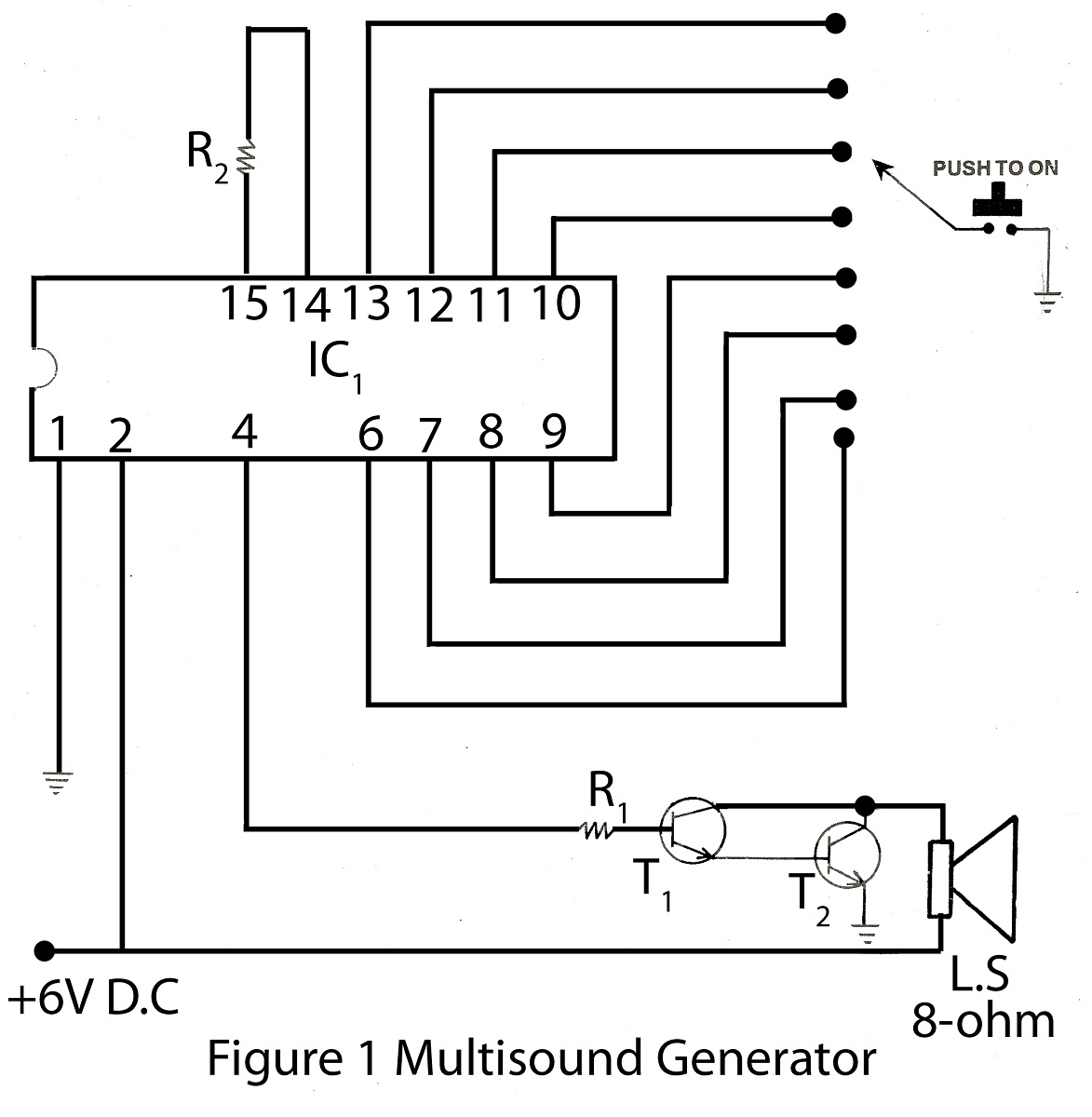
The multisound generator is an intriguing project within the alarm system series. This generator produces eight different types of sounds, and it includes a circuit diagram for various electronic projects. The multisound generator circuit is designed to create a variety...
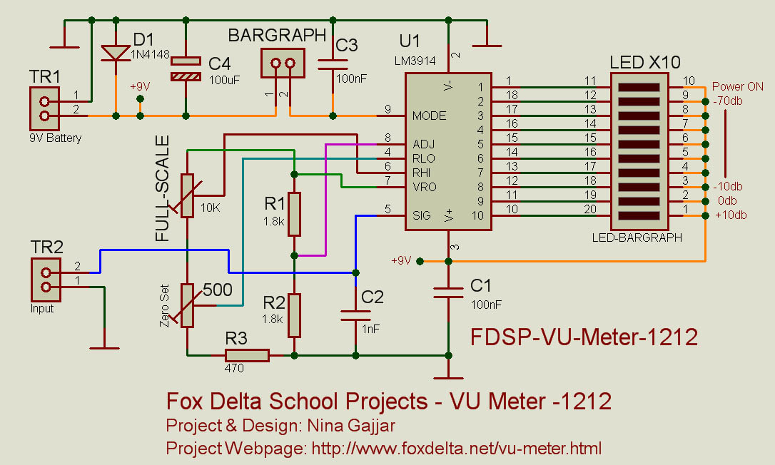
This simple VU meter can be utilized in a variety of projects. Since traditional electromagnetic VU meters are either no longer available or prohibitively expensive, this design employs the LM3914 integrated circuit and ten LEDs, allowing for versatile application...
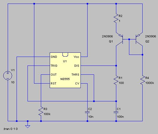
The typical BPM range for music is between 40 and 240 BPM, corresponding to periods of 1500 ms and 200 ms, respectively. A BPM of 120 equates to a period of 500 ms. The circuit requires a resistor R4...
This project utilizes an LM3915 bar-graph integrated circuit (IC) to drive two sets of ten LEDs, providing a 30 dB range. The circuit features an additional 20 dB range enabled by an automatic gain control, allowing for high sensitivity...
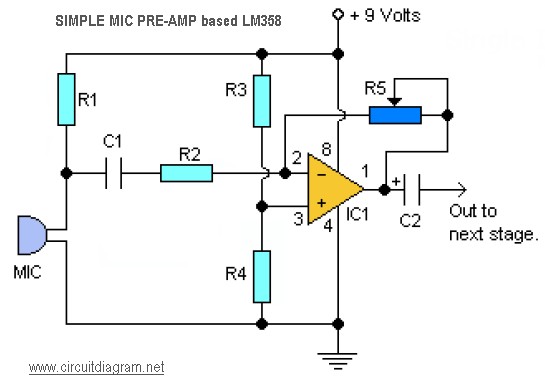
This is a simple audio microphone preamplifier circuit based on a single LM358 IC. The circuit is straightforward, cost-effective, and easy to construct. The component parts list includes: R1, R3, R4 = 10K; R2 = 1K; R5 = 100K-1M...
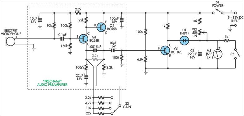
This circuit can be considered a straightforward alternative to the Sooper Snooper device discussed in this issue. It is based on the PreChamp preamplifier featured in the July 1994 issue of SILICON CHIP. This circuit can be utilized to...