
simple one wire touch detector

The circuit operates based on the principle of a capacitive touch sensor. When a user touches the metal plate, it alters the capacitance at the input of the Schmitt trigger, which is configured to provide a clean digital output. The voltage divider, composed of resistors R1 and R2, sets a reference voltage that defines the threshold for the Schmitt trigger's switching behavior.
Resistor R1 is connected to the metal plate, while R2 is grounded, forming a voltage divider that provides a varying voltage to the Schmitt trigger input depending on the capacitance introduced by the user's touch. The Schmitt trigger's hysteresis characteristics ensure that the output toggles cleanly between high and low states, minimizing false triggering due to noise or rapid changes in input.
The capacitor serves to filter out high-frequency noise, ensuring stable operation in environments with potential RF interference. LED1 provides a visual indication of the circuit's activation status, while the current-limiting resistor R3 protects the LED from excessive current, ensuring longevity and reliability.
Overall, this circuit exemplifies a straightforward yet effective design for touch-sensitive applications, suitable for various electronic projects requiring user interaction.This simple circuit can be used to activate whatever you like, for example, by connecting it to microcontroller, relays, secret alarms, robot applications or just turn on LED1 which lights up as long as you touch the metal plate. The circuit consists of voltage divider R1 and R2, one Schmitt trigger/inverter gate from a 40106 IC, a small capacitor to keep strong RF at bay and LED1 with current limiting resistor R3.
The metal plate is connected via a wire to R1. R1 and R2 together form a voltage divider.. 🔗 External reference
Related Circuits
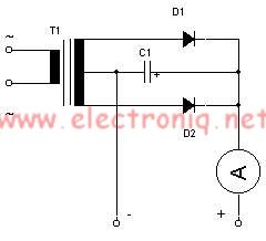
This simple lead-acid battery charger requires a center-tapped transformer (12V 0V 12V) capable of delivering a current of 5 amperes, two diodes, and one capacitor. To charge the batteries, the positive and negative terminals from the charger must be...
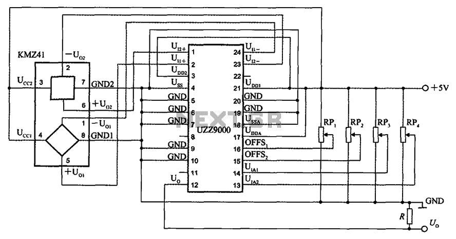
The UZZ9000 KMZ41 detection circuit is configured based on the voltage output type and angle. It operates with a +5V power supply. Potentiometers RP1 and RP2 are used for offset voltage adjustment, while potentiometers RP3 and RP4 are utilized...
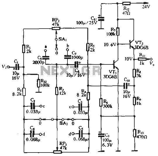
An attenuation switch is utilized to modify the pitch of a feedback control circuit's transition frequency, specifically for two treble controls. RP3 is designated for bass control, while SA1 and SA2 are employed to adjust the high bass control...
This circuit is designed to detect incoming calls on a cellular phone, even when the phone's ringer is turned off, by utilizing a flashing LED indicator. The device should be positioned a few centimeters away from the cellular phone,...
The internal telephone circuit is depicted below. By making minor enhancements to a toy telephone, it can be transformed into a functional internal telephone. This device comprises several components, including the phone unit, a decoding circuit, a ringing circuit,...
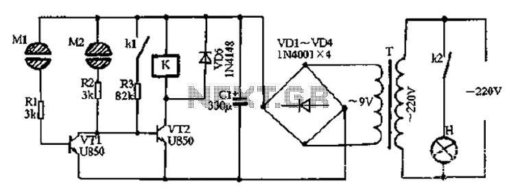
After the power is turned on, 220V AC is stepped down by transformer T. The output is then rectified by the VD1 to VD4 bridge rectifier and filtered by C1 to produce approximately 10V DC voltage for the Darlington...