
Simple phase detector

The circuit functions as a phase detector, utilizing an enabled inverter configuration to ascertain the relationship between two input signals, A and B1. The inverter's output, Y, operates based on the logical state of input A. When A is high (logic 1), the output Y reflects the state of B, effectively enabling the transmission of B's logic level. Conversely, when A is low (logic 0), the output Y is forced to a low state (logic 0), rendering it independent of B's state.
Connecting the signals A and B1 to the inputs of the circuit results in the generation of a pulse train signal at the output. The duration of these pulses is directly related to the phase difference between the two input signals. This relationship allows the circuit to measure phase differences within a range of 0 to 180 degrees accurately. The output pulse train can be analyzed to determine the timing discrepancies between A and B1, facilitating phase measurements critical in various applications, including signal processing and communication systems.
Moreover, the circuit can be enhanced by incorporating an AND gate to further analyze the phase relationship. The leading and lagging positions of the signals can be identified, providing additional context to the phase measurement. By evaluating both the phase difference and the leading/lagging information, a complete understanding of the phase relationship between the two signals can be achieved, extending the measurement capabilities to a full 360-degree range. This comprehensive analysis is essential for applications requiring precise synchronization and timing between multiple signals.The operation of the circuit is like an enabled inverter, that is, the output Y = B provided A is high. If A is low, output is low (independent of the state of B). When the signals A and or B1 are connected to the inputs A and of this gate the output Y is a pulse train signal (shown a Y or Yl) which has a pulse duration equal to the phase difference between the two signals.
The circuit is directly suitable for phase difference measurement from zero to 180°. This performance is similar to the circuits like the Exclusive OR gate used for this purpose. With this method leading and lagging positions of the signals can also be found using an AND gate. Phase difference measured along with the leading and lagging information gives complete information about the phases of the two signals between zero and 360°.
Related Circuits
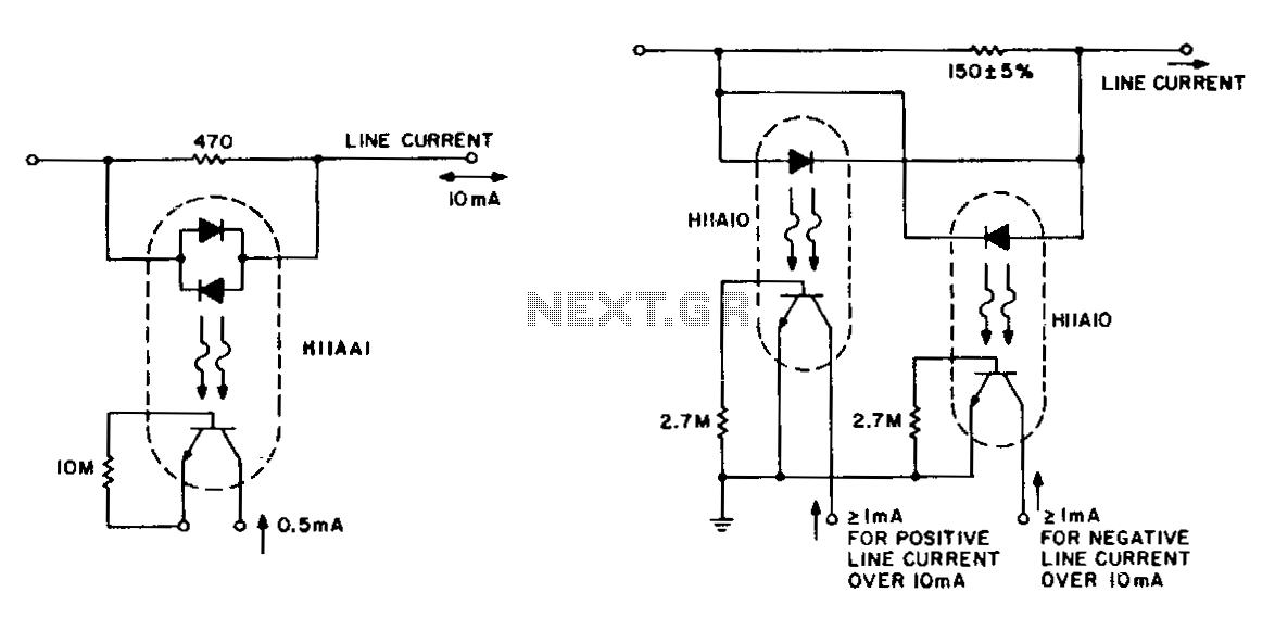
The detection of line-current flow and its indication at an electrically remote point is essential for line status monitoring in various telephone systems and auxiliary systems. The monitoring circuit must minimally unbalance or load the line, while also being...
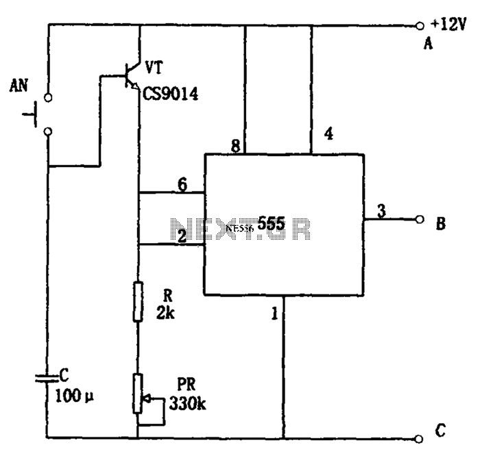
The circuit features a straightforward long timing mechanism. Activating switch AN initiates the timing process, while tone PR allows for timing adjustments. The timing range spans from 3 minutes to 220 minutes. With a capacitance value of 2200 µF,...
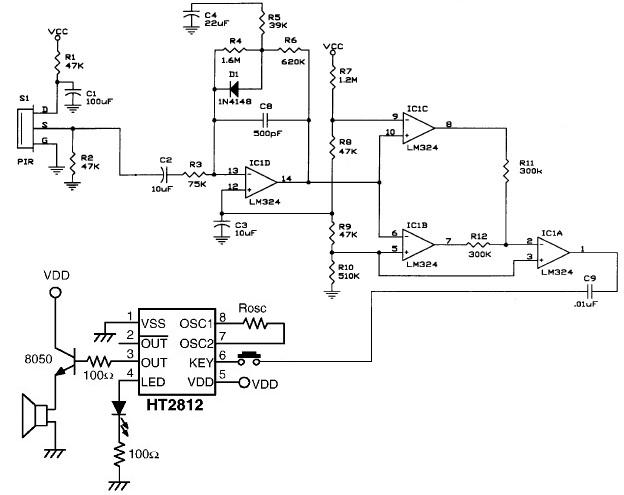
The presented schematic illustrates the construction of a simple PIR motion detector sensor. PIR sensors are capable of detecting motion and are primarily utilized to determine if a person has entered or exited the sensor's range. These sensors are...
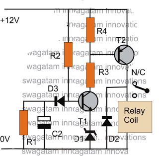
The post discusses a simple delay ON circuit that enables a connected load at the output to be activated with a predetermined delay after the power switch is turned ON. This circuit can be utilized in various applications that...
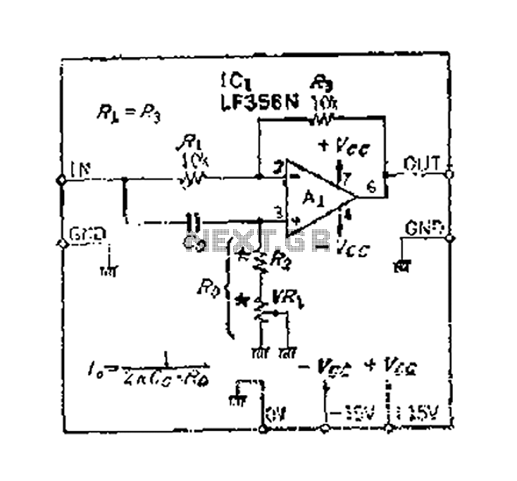
An accurate phase shift of 90 degrees can be achieved using a variable resistor (VR) and an operational amplifier (op-amp). The adjustment allows for a specific frequency to be manipulated. The phase shift can range from 180 degrees to...
The monostable flip flop, sometimes called a 'one shot' is used to produce a single pulse each time it is triggered. It can be used to debounce a mechanical switch so that only one rising and one falling edge...