
Simple Power Saving Devices

The described power-saving device operates on the principle of power factor correction, which enhances the efficiency of electrical systems by reducing the phase difference between voltage and current in AC circuits. The circuit typically includes a coil that acts as a current sensor, measuring the AC load. This coil is often wound around a core material that enhances its inductive properties, ensuring accurate current readings.
The capacitor in the circuit plays a crucial role in storing and releasing electrical energy, thus smoothing out the current waveform and reducing harmonics. The choice of capacitor is essential, as higher-quality capacitors can handle greater voltage and current without failure, ensuring reliability and longevity in the circuit's operation. The switch (SW) serves as a safety mechanism, allowing for easy disconnection of the circuit during maintenance or in case of an anomaly, preventing potential damage to the components.
For effective implementation, the circuit should be designed with careful consideration of the ratings of all components, ensuring they are suitable for the expected load. Proper insulation and housing in a plastic box are necessary not only for safety but also to protect the components from environmental factors. This setup can be particularly beneficial in residential applications, where electricity consumption can be significantly reduced, leading to lower energy bills and a reduced carbon footprint.If you need a tool to save electricity you use, so in this article a simple power saving device circuit diagram is very suitable for you to test. Basically, this tool can really save electricity in your home from 10-25%. Work of this tool is simply to reduce the number of cosines of the AC current curves which will be read on a gauge to measure a
mile in your home. The power saving device will work if there is an AC load through a coil of wire sensors to measure the amount of AC current through it. Or a scientific theory is how we can reduce the possibility of the largest peak (peak of the curve of AC (sine-cosine) to read so low.
power saving device component which affects the flow of AC and condenser or capacitor or inductor loop. You can do is flow air conditioner filters before entering the electricity network in your home. Here is a schematic power saving device drawing: Create the circuit in a plastic box. then use a capacitor with good quality, the more expensive the better. to SW is functioning as a safety in case of short circuiting due to the capacitor. 🔗 External reference
Related Circuits
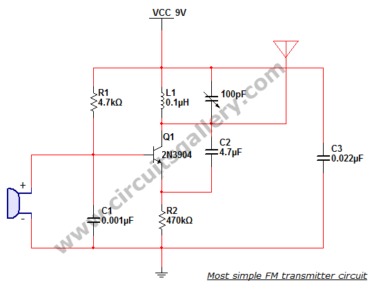
This is the simplest single transistor FM wireless transmitter circuit ever posted in CircuitsGallery. In the field of telecommunications, frequency modulation (FM) transmits information by altering the frequency of a carrier wave based on the message signal. FM utilizes...
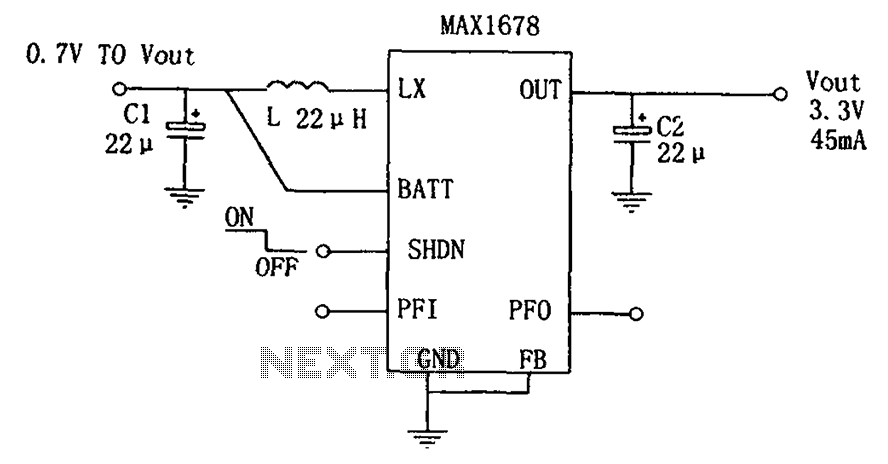
As depicted in the figure, this circuit is suitable for high-efficiency single-cell battery power boosting. It comprises a MAX1678 integrated circuit and three external components. The MAX1678 is designed for low-power applications and features an ultra-small 8-pin MAX package....
This is a high quality power supply with a continuously variable stabilized output adjustable between 0 and 30VDC. The LM 723 is the heart of the power supply which drives the BD137 and then the 2N3055. The circuit provides...
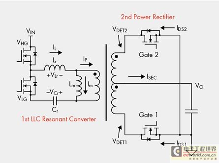
The designer is looking for a solution with higher efficiency and lower power consumption in order to minimize unnecessary energy loss. The approach involves using syntony inductance to harmonize the capacitive LLC syntony converter, employing zero voltage switching (ZVS)...
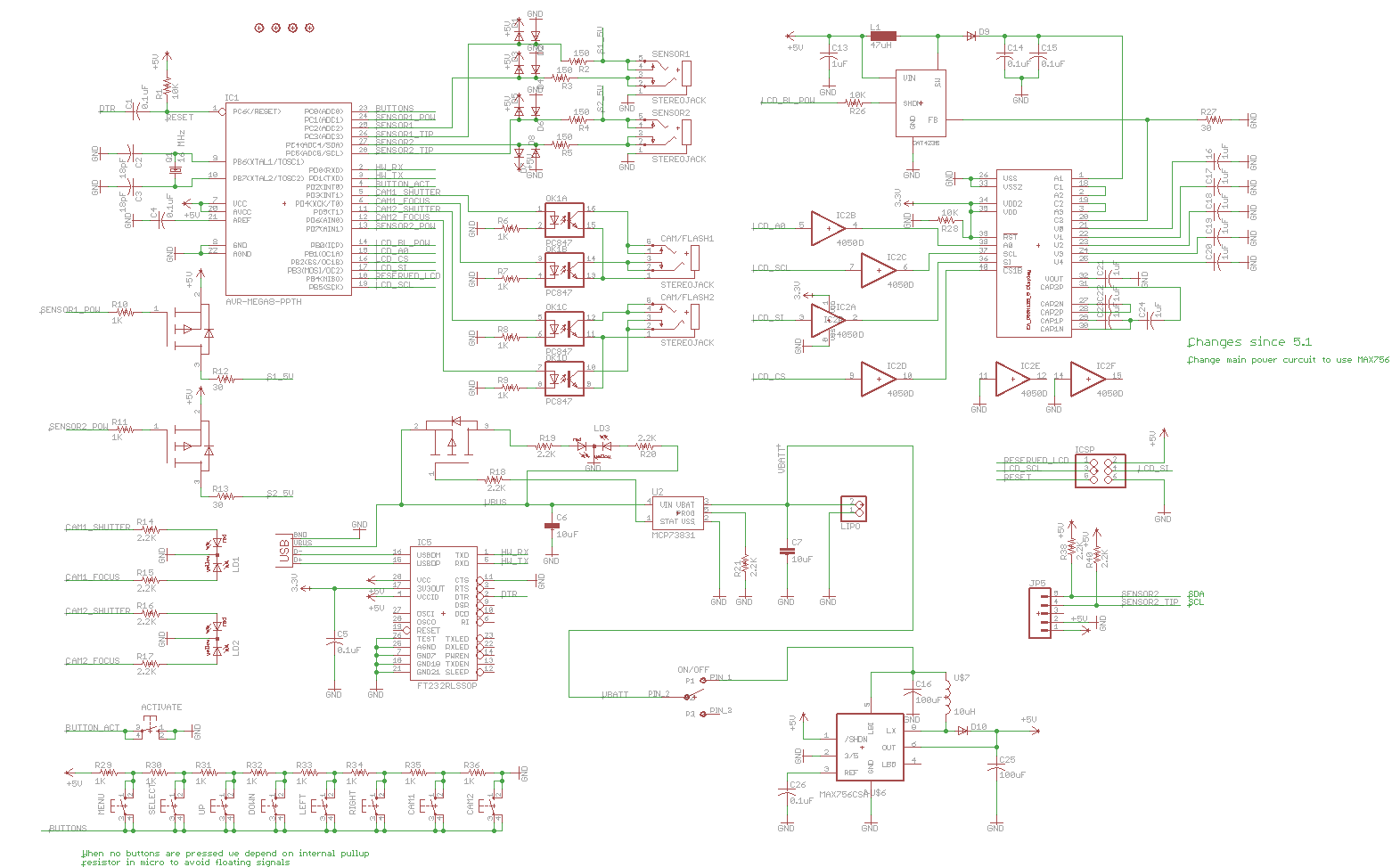
Previously, a linear regulator was used, but a Max756 boost converter is now in operation. An output ripple of 0.1 to 0.3V is observed in the current, while the Max756 datasheet indicates an expected ripple of about 50 mA....
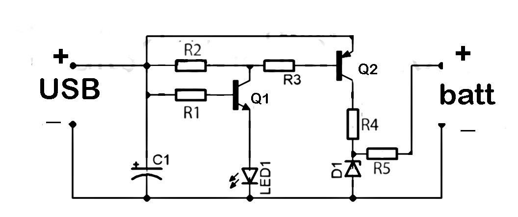
This document discusses the series used in USB connections for charging batteries. The output voltage ranges from 4.7 volts to 5 volts DC, which is suitable for charging mobile phones and other battery types. The circuit described enhances the...