
Simple continuity tester

The described circuit functions as a resistance measurement device that utilizes the principles of a multivibrator configuration. The multivibrator is constructed using two transistors, Q1 and Q2, which create an oscillating signal. The frequency of this oscillation is modulated by the resistance present between the designated test points. This allows the circuit to produce a tone whose pitch varies with the resistance being measured.
In practical applications, the circuit can effectively measure a wide range of resistances, from hundreds of kilohms down to small variations in the tens of ohms, making it suitable for both high and low resistance measurement tasks. The sensitivity of the circuit is particularly beneficial in low-resistance scenarios, where small changes in resistance can be detected, providing precise feedback about the resistance under test.
The output stage of the circuit is comprised of transistors Q3 and Q4, which are configured to drive an audio output device such as a small loudspeaker or a telephone earpiece. This stage amplifies the oscillating signal generated by the multivibrator, converting the frequency variations into audible tones. The resulting sound output serves as an intuitive indication of the resistance level, allowing users to easily interpret the measured values through auditory feedback.
This resistance tester is particularly useful in applications where visual measurement tools may be impractical, enabling technicians to perform resistance measurements effectively while focusing on other tasks. The design emphasizes simplicity and functionality, ensuring that it can be easily implemented in various electronic testing environments.The pitch of the tone is dependent upon the resistance under test. The tester will respond to resistance of hundreds of kilohms, yet it is possible to distinguish differences of just a few tens of ohms in low-resistance circuits. Ql and Q2 form a multivibrator, the frequency of which is influenced by the resistance between the test points.
The output stage Q3 and Q4 will drive a small loudspeaker or a telephone earpiece.
Related Circuits
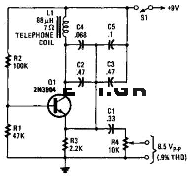
An 88 mH surplus telephone toroidal coil is utilized in a 1 kHz oscillator. It can provide up to 8 V peak-to-peak into a high-impedance load. The total harmonic distortion (THD) is 0.9%. The circuit employs an 88 mH toroidal...
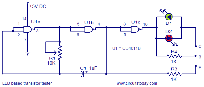
This circuit represents a simple transistor tester that utilizes two LEDs to indicate the condition of a transistor. It is capable of testing both PNP and NPN transistors. The core component of the circuit is the quad 2-input CMOS...
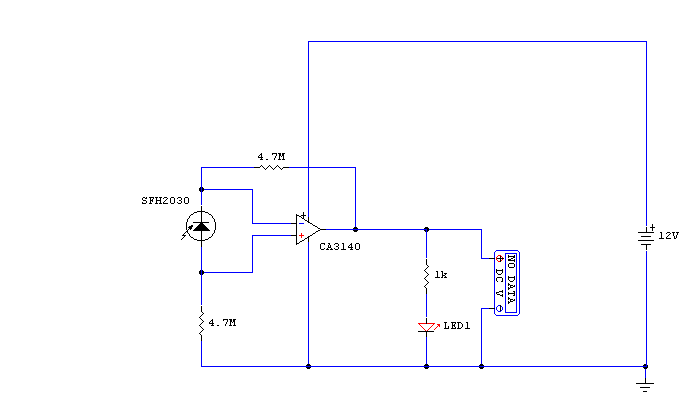
A photodiode, SFH2030, serves as an infrared sensor. A MOSFET operational amplifier, CA3140, is utilized in differential mode to amplify the current pulses from the photodiode. LED1, an ordinary colored LED, illuminates when infrared radiation is detected. The output...
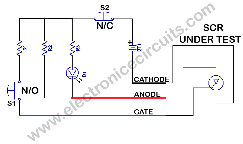
SCR Tester Circuit. The device under test, cathode, anode, and gate are connected to the unit's cathode, anode, and gate terminals. The SCR tester circuit is designed to evaluate the functionality of Silicon Controlled Rectifiers (SCRs) by facilitating connections to...
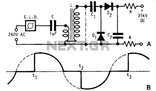
A light dimmer, a 1 µF capacitor, and a 12 V car ignition coil form a simple line-powered high-voltage generator. The current in the dimmer is illustrated in Fig. B. During the time intervals tp to t2, determined by...
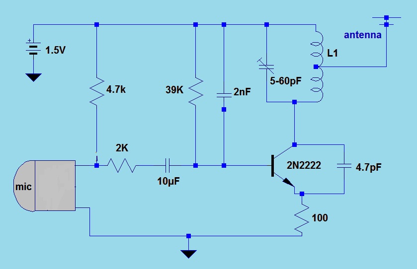
This simple FM (frequency modulation) transmitter is powered only by a 1.5V battery and utilizes a single transistor. The frequency of this transmitter is controlled by the L-C resonance circuit and operates within a range of 80 to 110...