
Simple pulse width modulation circuit

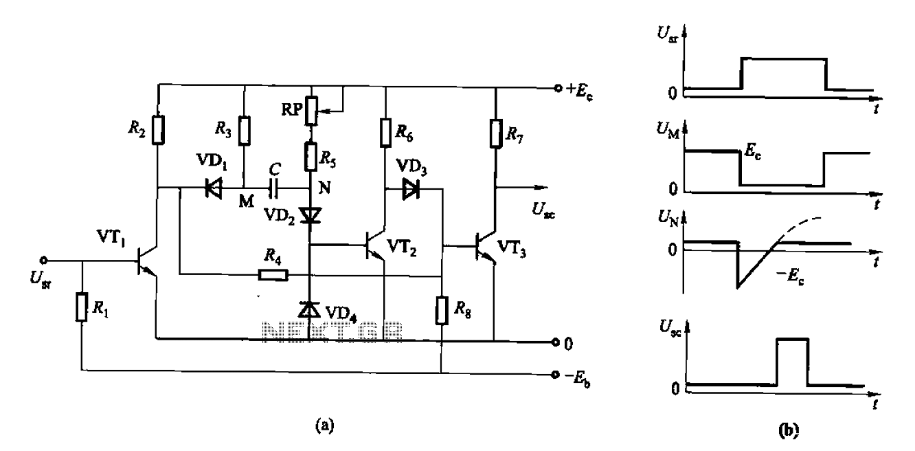
The pulse width modulation (PWM) circuit described operates using an operational amplifier configured as a multivibrator, which generates a square wave output. The circuit achieves a 50% duty cycle, meaning that the output signal is high for half of the cycle time and low for the other half. This symmetrical output is pivotal in applications where precise control of power delivery is necessary, such as in motor speed control or light dimming.
The frequency of oscillation, denoted as f0, is a critical parameter in this design. It is influenced by the resistive and capacitive components in the circuit. Specifically, the formula f0 = 1/(2R4C1) * ln(1 + (2R2/R3)) illustrates the relationship between the resistors R2, R3, and R4, as well as capacitor C1. The logarithmic term accounts for the hysteresis effect introduced by the feedback configuration of the operational amplifier.
In situations where the circuit is not connected to resistor R1, the frequency can be simplified further. The condition where [1 + (2R2/R3)] equals 2.718 indicates that the circuit is operating at a natural logarithm base, simplifying the frequency to f0 = 1/(2R4C1). This characteristic allows for the design to be adaptable; by varying the external voltage applied to the threshold levels, the duty cycle can be finely tuned. This adjustment is facilitated through the resistor R1, which modulates the voltage levels at the operational amplifier's input, thus influencing the output pulse width.
In summary, this pulse width modulation circuit offers a versatile solution for generating PWM signals with adjustable duty cycles. The integration of an operational amplifier as a multivibrator, combined with the strategic use of resistors and capacitors, allows for precise control over the output signal characteristics, making it suitable for a wide range of electronic applications.The simple pulse width modulation circuit is as shown in the figure. It uses the operational amplifier to form the multivibrator, so we can get the positive and negative symmetrical oscillation output signal with the duty ratio of 50%. If we change the threshold voltage from external, we can realize the pulse width modulation. If this circuit is n ot connected with the resistor R1, the oscillation frequency f0 is decided by the cycle of the hysteresis voltage, f0=1/2R4C1ln(1+(2R2/R3). If [1+(2R2/R3)]=2. 718, the f0=l/(2R4C1), so we can change the duty ratio by using the external voltage to move the ±UTH through R1.
🔗 External reference
Related Circuits
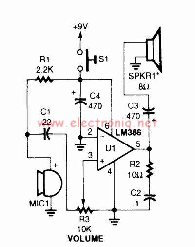
A voice amplifier can be designed using the LM386 power amplifier, which is intended for low voltage consumer applications. This simple circuit features variable gain and volume control. The gain is set internally to 20 to minimize the number...
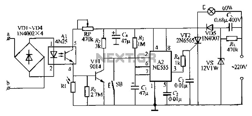
The lamp base circuit integrates an NE555 timer and optocouplers to automatically activate the light when a phone call is received at night. The lamp will self-extinguish after a delay. Additionally, a switch allows manual control of the lamp....
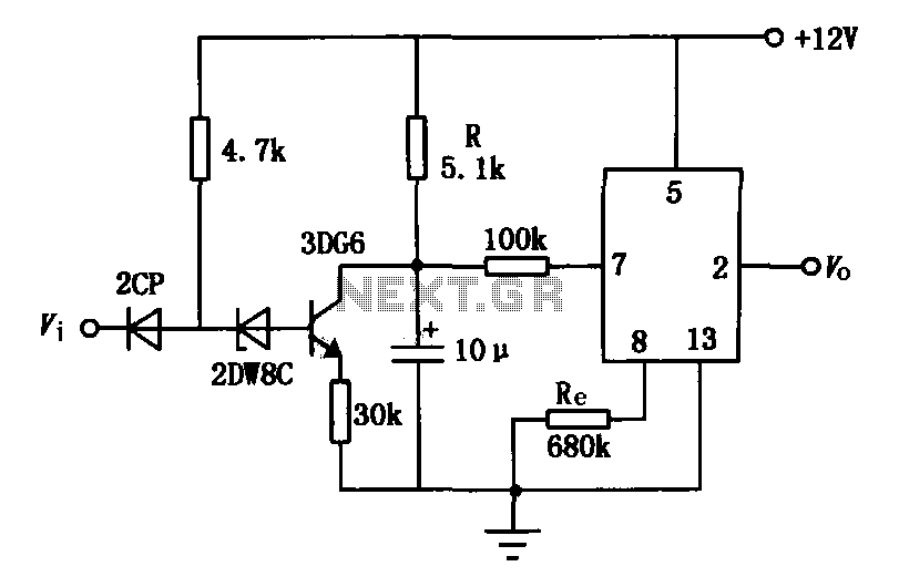
The delay application circuit is depicted in Figure JEC-2, which consists of two components. When the input transitions from logic level 0 to 1, the output also changes to 1 immediately. However, when the input transitions from high level...
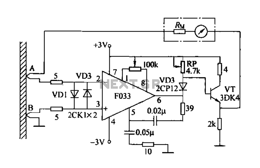
Detecting electrical equipment sometimes requires disconnecting the circuit in series for more accurate measurements of electrical current using an ammeter. However, restoring the circuit to its original state is necessary, as it can affect the normal operation of electrical...
The circuit described is a discharge delay circuit that offers a longer delay compared to a standard rechargeable delay circuit, while also maintaining relatively high accuracy. The schematic diagram illustrates the input and output waveforms. Typically, when there is...
When the infrared receiver tube PH302 receives a signal from the remote control, the CX20106A selected frequency amplifier outputs a low-frequency signal. The low-level signal charges capacitor C through diodes D and R, causing the negative side potential of...