
Simple Pyro RF Receiver (27 MHz) - Signal Mixing
 - Signal Mixing")
The regenerative front-end receiver circuit is designed to capture and amplify weak signals transmitted over a specified frequency range. The LC tuning circuit serves as a selective filter, allowing only the desired frequency to pass while attenuating unwanted signals. This tuning circuit is essential for optimizing signal reception, particularly in environments with substantial background noise.
After the LC circuit, the DC blocking capacitor is implemented to prevent any DC voltage from affecting the subsequent amplification stages. This ensures that only the AC component of the signal, which contains the information, is passed through for further processing.
In the first amplification stage, a transistor-based amplifier or operational amplifier is typically employed to boost the signal strength. The increase from 22 mV to 218 mV indicates that the amplifier is effectively enhancing the signal, but it is still below the threshold required for the 555 timer comparator to function correctly. The 555 timer comparator is a versatile device used for signal processing, timing applications, and as a pulse-width modulation generator. For optimal operation, the input signal must be above a certain voltage level, hence the need for additional amplification.
To achieve the necessary signal level, a second amplification stage can be incorporated. This stage may utilize a more robust amplifier configuration, such as a multi-stage amplifier or a dedicated RF amplifier, designed to provide higher gain and improve signal integrity. The output of this second stage should be monitored to ensure that it meets the required specifications for the 555 timer comparator input, enabling effective signal processing and further downstream applications.
Overall, the described circuit illustrates the critical stages of signal reception and amplification, highlighting the importance of each component in achieving a reliable output from the regenerative front-end receiver circuit.After the wizardry that is our standard renegerative front-end receiver circuit, we will be able to see some initial output receiver from our transmitter. The point in the schematic we`ll look at first is right after the LC tuning circuit and DC blocking capacitor: On the Left side there is a picture of that point when nothing is being transmitte
d. Compare that to the Right side which shows what that point in the schematic looks like when the transmitter is actively transmitting. You can see our carrier is making it through the LC circuit as it should be, vs. the background noise measurement, which is just noise. Since our signal made it through the LC tuning circuit like we expected, we now need to amplify the heck out of it to get it back to a level where you can actually use it, below you can see the output from the first amplification stage: This output looks a lot larger than our 22mv input at about 218mv, but its not yet good enough to be used with our 555 timer turned comparator.
So let`s amplify the signal once more. 🔗 External reference
Related Circuits
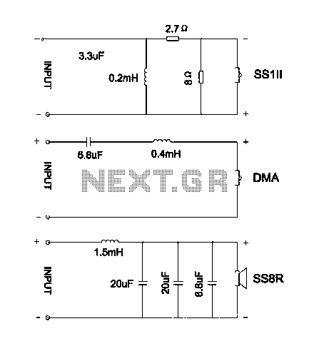
The divider acts as the speaker's brain and is crucial for sound quality. The music amplifier's output signal must be processed through a wave filter element to divide it into specific frequency signals for each unit. A scientifically and...
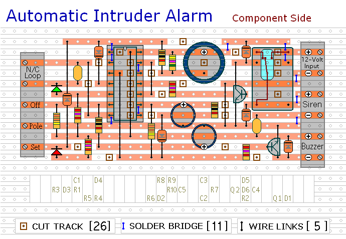
This circuit includes automatic exit and entry delays, a timed bell cut-off, and a system reset feature. It is designed to work with standard normally-closed input devices such as magnetic reed contacts, micro switches, foil tape, and passive infrared...
This is a simple game circuit designed for multiplayer enjoyment. The objective is to score one hundred points within a limited timeframe. To restart the game, the S1 button switch must be pressed. It is important to ensure that...
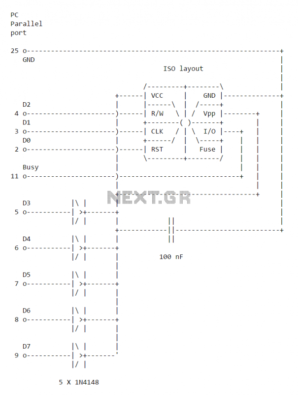
This simple PC Smartcard reader was shown in Electronics Design magazine February 17, 1997 issue on page 172 in the ideas for design section. The circuit is designed by Jose Carlos Cossio and is based on simple smartcard reader...
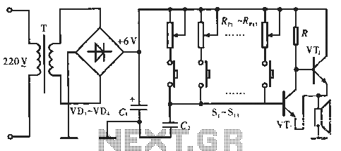
The circuit includes resistors Rp1 to Rp13, which serve dual purposes: they scale the resistance for the keyboard and function as timing resistors for the oscillator. Capacitor C2 acts as a wide discharge capacitor, while switches S1 to S13...
The MSF transmitter transmits time data bit-by-bit over 60 seconds each minute by modulating a 60 kHz carrier frequency. It employs a continuous wave (CW) signal. Two bits are sent every second through variations in the duration and number...