
Simple RF Detector for 2 m

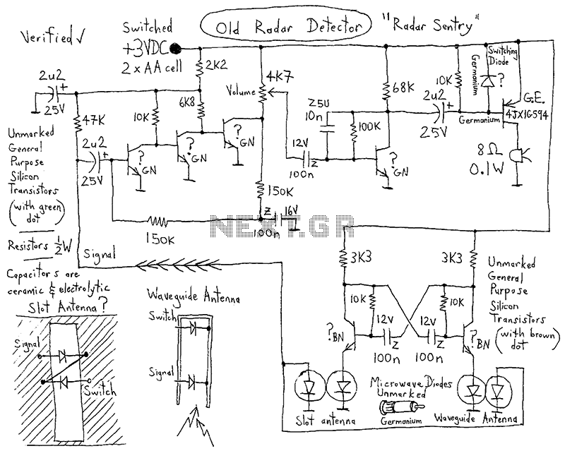
This circuit is designed to identify and measure radio frequency (RF) radiation emissions, which can indicate issues such as faulty connections, damaged cables, or insufficient shielding in electronic devices. The core component of the circuit is a sensitive RF detector, typically implemented using a diode or a specialized RF sensor module.
The circuit operates by capturing the RF signals present in the environment and converting them into a measurable voltage output. This output can then be displayed on an analog or digital meter, allowing the user to assess the level of RF radiation.
To enhance the sensitivity and accuracy of the measurements, the circuit may include additional components such as amplifiers, filters, and capacitors. An operational amplifier can be used to boost the signal strength, while a band-pass filter can help isolate the frequency range of interest, eliminating unwanted noise from other sources.
Furthermore, the design may incorporate a microcontroller to process the detected signals, providing a more sophisticated analysis of the RF emissions. The microcontroller can be programmed to trigger alarms or visual indicators when radiation levels exceed predefined thresholds, making the circuit not only a diagnostic tool but also a safety device.
Power supply considerations are also crucial; the circuit can be powered by batteries for portability or connected to a stable power source for continuous monitoring. Proper grounding and shielding techniques should be employed in the circuit layout to prevent interference and ensure accurate readings.
Overall, this RF radiation detection circuit serves as an essential tool for troubleshooting and maintaining the integrity of RF equipment, ensuring compliance with safety standards and optimal performance.This simple circuit helps you sniff out RF radiation leaking from your transmitter, improper joints, a broken cable or equipment with poor RF shielding. Th. 🔗 External reference
Related Circuits

This circuit decomposes an input voltage signal into two components: (1) the absolute value and (2) the polarity or sign (+ or -). It is capable of handling direct input voltages as well as alternating voltages up to several...

A simple FM transmitter utilizing a single transistor. Mini FM transmitters are commonly regarded as one of the fundamental circuit types for beginners in amateur electronics. When constructed correctly, they offer clear wireless sound transmission via a standard FM...

This article describes how to build a simple yet effective sound trigger for cameras or flashes. The circuit allows for experimentation with high-speed photography. The sound trigger circuit is designed to activate a camera or flash unit in response to...

The detector is designed to sense and signal to another circuit when an appliance is connected to the mains voltage. For this purpose, an optocoupler, IC1, is utilized. The circuit employs an optocoupler (IC1) to provide electrical isolation between the...
The LED phototransistor light gate should be mounted approximately 1 to 2 cm apart, within a rigid housing. It was mounted on a brass piece attached to the circuit board. The housing must accommodate the compass without obstructing the...

A very simple dimmer circuit with only the essentials. In this circuit, the values are given for a BT138 at 220V AC. For 115V AC, experimentation with values may be necessary. R1 can vary from one triac to another;...