
Temperature to Digital ConverterCircuit using LM35

The described circuit employs the LM35 temperature sensor, a precision integrated circuit that outputs an analog voltage proportional to the temperature in degrees Celsius. The LM35 is known for its ease of use, as it does not require any external calibration and offers a linear output of 10 mV per degree Celsius.
In this configuration, the bypass capacitor serves a critical role in stabilizing the power supply voltage at the VIN pin of the LM35. By connecting the capacitor from VIN to ground, it filters out any high-frequency noise that may be present in the power supply line, thereby ensuring stable operation of the sensor. Proper bypassing is essential for accurate temperature readings, as fluctuations in supply voltage can lead to erroneous output signals.
The series RC damper included in the circuit is designed to mitigate any potential overshoot or ringing in the output signal. This is particularly important when interfacing the LM35 with an analog-to-digital converter (ADC), as rapid changes in temperature can produce transient spikes in the output voltage. The RC damper works by introducing a time constant that smooths out the response of the circuit, allowing for more stable and reliable readings.
Overall, the combination of the LM35 sensor, the bypass capacitor, and the series RC damper creates a robust temperature measurement system that can be effectively integrated into various electronic applications, such as environmental monitoring, HVAC systems, and temperature control mechanisms.Above circuit shows Temperature to Digital Converter diagram using this LM35 sensor with a useful bypass capacitor from VIN to ground and a series RC damper 🔗 External reference
Related Circuits
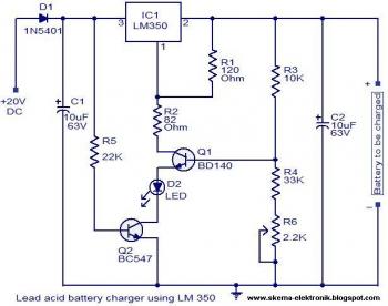
The circuit is designed as a constant voltage source with a negative temperature coefficient. The transistor Q1 (BD 140) serves as the temperature sensor, while transistor Q2 prevents battery discharge through resistor R1 when mains power is unavailable. The...

A high-power and efficient 100W power amplifier electronic project can be designed using the STK404 audio power amplifier hybrid ICs. These ICs consist of optimally designed discrete component power amplifier circuits that have been miniaturized using SANYO's unique insulated...
This circuit is designed to provide an inexpensive way to create a High Impedance Voltmeter while making use of an inexpensive analog or digital multimeter. When measuring voltages in high resistance circuits, the resistance of the voltmeter itself has...
The ISD1000A is a Direct Analog Storage device which allows you to store 20 seconds worth of voice data on an IC chip which can be played back anytime. The data stored will stay in memory even if the...
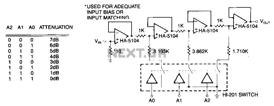
The first stage is a simple buffer used to isolate the signal source from the following attenuator stages. Each subsequent stage is preceded by a voltage divider formed by two resistors and a CMOS switch. When the CMOS switch...
This simple LED flasher circuit will alternately turn ON and OFF two LEDs. The first LED will illuminate when the second LED is OFF for a certain duration, and then the process will repeat. The LED flasher circuit operates using...