
Wien-Bridge Oscillator
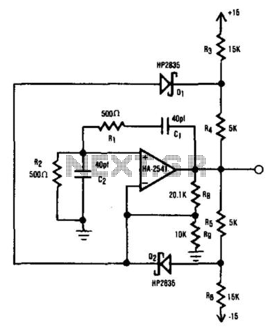
The HA2541 oscillator circuit operates by utilizing a combination of resistive and capacitive components to generate and stabilize oscillations. The primary function of the HA2541 is to produce a sine wave output, and its design allows it to achieve frequencies up to 50 MHz effectively.
The circuit includes a feedback network formed by R1, C1, R2, and C2, which is critical for establishing the oscillation condition. The feedback network must provide a gain slightly above three to sustain oscillation. The gain is adjusted using the resistors R8 and R9, which fine-tune the feedback loop.
The diode limiting provided by D1 and D2, along with resistors R3 to R7, helps to shape the waveform, ensuring that the output remains within desired amplitude levels and prevents distortion. This diode limiting is essential for maintaining the integrity of the sine wave output, especially at higher frequencies.
The choice of components, particularly the values of R1, C1, R2, C2, R8, and R9, directly affects the frequency stability and quality of the output waveform. It is crucial to select these components carefully to optimize performance and achieve the desired frequency response.
Overall, the HA2541 oscillator circuit is a robust design suitable for applications requiring high-frequency sine wave generation, leveraging the capabilities of the HA2541 operational amplifier in conjunction with passive components to achieve reliable and stable oscillation. The HA2541 is well-suited for use as the heart of an oscillator. In spite of the rudimentary diode limiting that is provided by R3 through R7 and D1 and D2, a good-quality sine wave of 40 MHz is readily attainable with an upper limit of 50 MHz, which exceeds the unity-gain bandwidth of HA-2541. Rl/Cl and R2/C2 provide the required regenerative feedback needed for adequate frequency stability. In theory, the feedback network requires a gain of three to sustain oscillation. However, the practical gain needed is just over three and is provided by R8 and R9. 🔗 External reference
Related Circuits

An exclusive-OR gate, IClD, converts a simple CMOS oscillator into a frequency-shift keying (FSK) generator. When the data input increases, IClD inverts, and negative feedback through R2 reduces the circuit's output frequency. A low input leads to positive feedback,...
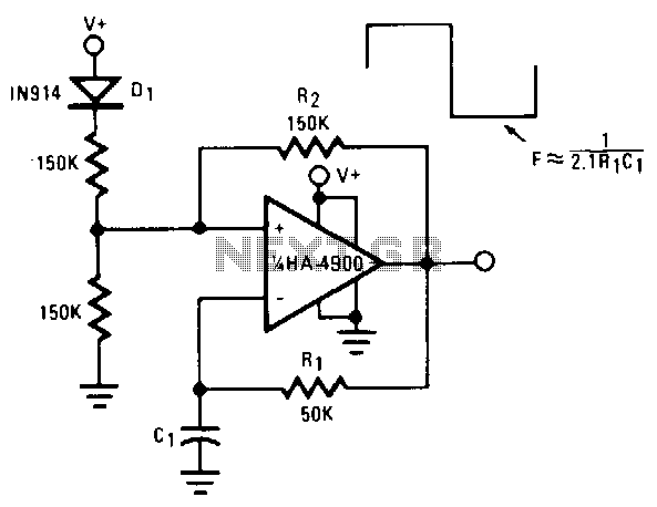
This self-starting fixed-frequency oscillator circuit provides excellent frequency stability. R1 and C1 form the frequency-determining network, while R2 delivers the regenerative feedback. Diode D1 improves stability by compensating for the difference between VaH and VsurrLY. In applications where a...
Occasionally, there is a requirement to create a very basic oscillator. The circuit illustrated here is remarkably straightforward, utilizing only three components. The described oscillator circuit typically consists of a resistor, a capacitor, and a single transistor. The operation of...

The MAX2620 integrates a low-noise oscillator with two output buffers in a cost-effective, plastic surface-mount, ultra-small uMAX package. This device combines functions that are typically achieved with discrete components. The MAX2620 is designed for applications requiring precise frequency generation with...
Hand and body motions in proximity to the sensing antennas produce frequency changes in a Hartley oscillator operating at approximately 750kHz. The signal from this variable oscillator is mixed with a constant reference frequency in a ring modulator and...
This circuit appears to be a Schmitt trigger oscillator. Based on the configuration of the resistors and capacitor, it is likely functioning as a sawtooth wave generator, with resistors R2 and R3 influencing the slope of the rising and...
Warning: include(partials/cookie-banner.php): Failed to open stream: Permission denied in /var/www/html/nextgr/view-circuit.php on line 713
Warning: include(): Failed opening 'partials/cookie-banner.php' for inclusion (include_path='.:/usr/share/php') in /var/www/html/nextgr/view-circuit.php on line 713