
simple signal injector aids control loop analysis

The signal-injection circuit is designed to facilitate control-loop analysis by providing a stable and consistent signal across a frequency range from direct current (DC) to 200 kilohertz (kHz). The circuit's flat frequency response ensures that it can accurately inject signals without introducing distortion or frequency-dependent variations, making it suitable for testing and analyzing control systems.
Isolation from chassis ground is a critical feature of this circuit. This isolation helps to prevent ground loops and other noise issues that can affect the accuracy of measurements. By maintaining a floating ground reference, the circuit can be used in various environments without the risk of interference from external electrical noise.
The circuit can be constructed using a standard instrumentation amplifier, which is readily available in the market. Instrumentation amplifiers are preferred for their high input impedance, low output impedance, and excellent common-mode rejection ratio (CMRR). These characteristics make them ideal for accurately amplifying small signals while rejecting noise and interference.
To build the circuit, the instrumentation amplifier is configured to accept input signals and provide an output that can be injected into the control loop under test. Additional components such as resistors, capacitors, and possibly a power supply may be required to complete the circuit and ensure proper operation. Careful selection of these components will further enhance the performance and reliability of the signal-injection circuit.
Overall, this signal-injection circuit serves as a valuable tool for engineers and technicians involved in control system analysis and testing, allowing for precise signal manipulation and measurement across a critical frequency range.A signal-injection circuit for control-loop analysis is flat from dc to 200 kHz, isolated from chassis ground and easily constructed with a readily available instrumentation amplifier.. 🔗 External reference
Related Circuits
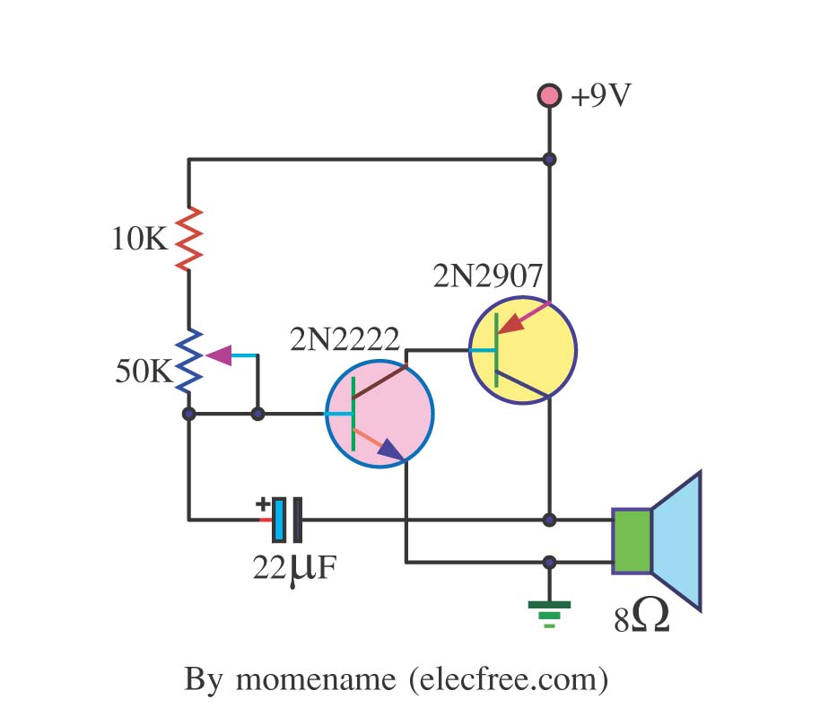
This is a simple tone oscillator generator. It uses the transistors 2N2222 and 2N2907 as the main components. The tone sound is controlled with a 50K ohm resistor (R2) and an 8-ohm speaker is utilized. The tone oscillator generator circuit...
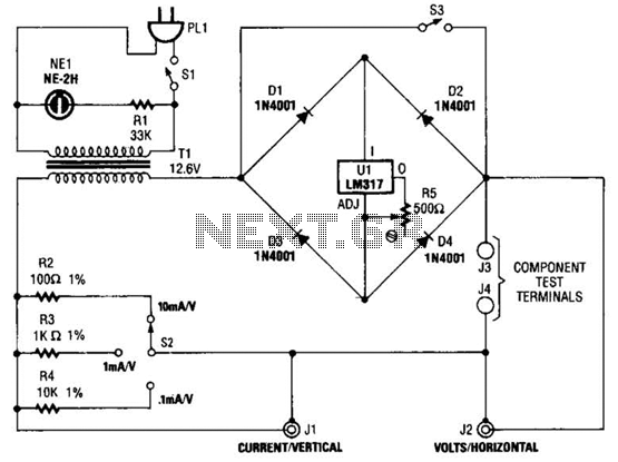
Useful for checking diodes, transistors, triacs, SCRs, resistors, and LEDs, this curve tracer should prove beneficial in the experimenter's lab. It displays the volt-ampere characteristic of a two-terminal device on an oscilloscope. This is a simple block diagram of...

An issue with CPLD and FPGA devices is that they have numerous I/O pins, resulting in schematics that quickly become overwhelmingly large. Different sections of the schematic have been partitioned to illustrate the motor control circuit, analog-to-digital converter circuit,...
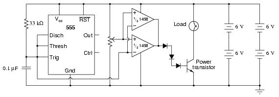
This circuit utilizes a 555 timer to generate a sawtooth voltage waveform across a capacitor, which is then compared to a steady voltage provided by a potentiometer using an operational amplifier (op-amp) configured as a comparator. The comparison of...
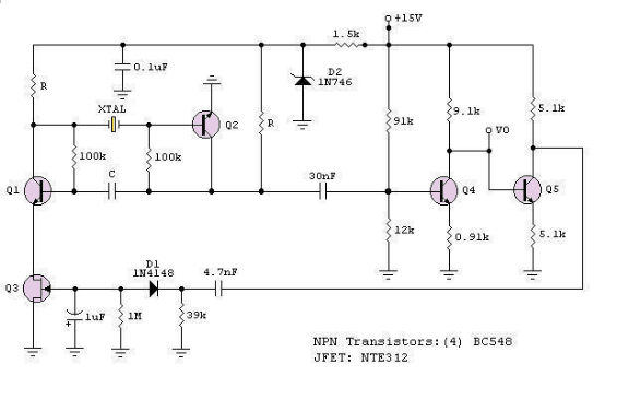
The RF engineer often needs an instrument that can reliably and quickly test a low-frequency quartz crystal unit. However, such equipment is challenging to find, and engineers frequently consult electronic circuit handbooks for schematics that can accomplish this task....
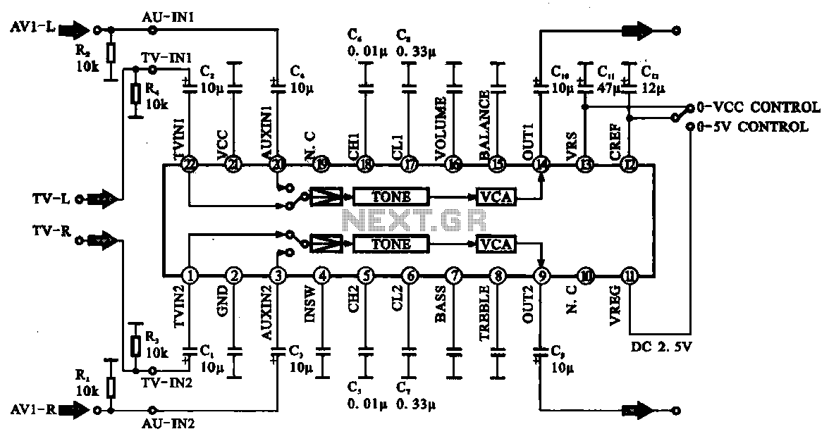
Audio signal control circuit. It illustrates a typical audio signal control circuit where two audio signals enter the integrated circuit through switching and tone controls (treble and bass), subsequently adjusting the output sent to the audio power amplifier. The audio...