
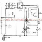
Simple Signal Tracer Circuit

The circuit under discussion utilizes an envelope detector, which is a fundamental component in demodulating amplitude-modulated (AM) signals. The envelope detector consists of a capacitor (C1), a diode (D1), and a resistor (R1). The primary function of this trio is to extract the envelope of the incoming modulated signal, effectively allowing the audio signal to be recovered from the carrier wave.
C1 serves to smooth the rectified output from D1, which is crucial for ensuring that the audio signal is clean and free from high-frequency noise. The value of C1 is selected based on the frequency of the input signal and the desired response time of the envelope detector. D1 is typically a silicon diode, chosen for its low forward voltage drop and fast switching characteristics, which are essential for accurately tracking the envelope of the incoming signal. R1 acts as a load resistor that determines the time constant of the circuit in conjunction with C1, influencing how quickly the circuit responds to changes in the input signal.
C2 is employed to couple the audio signal to the base of transistor Q1. This coupling capacitor ensures that the DC biasing of the transistor is not affected by the audio signal while allowing the AC audio component to pass through. The choice of C2's value is critical as it must be low enough to allow the full audio frequency range to be transmitted without attenuation.
R2 is an adjustable resistor that provides a means to control the gain of the circuit. By varying the resistance, the amount of feedback to Q1 can be altered, thus adjusting the amplification of the audio signal. This adjustability is vital for tailoring the circuit's performance to match the specific requirements of the application, whether it be for a low-sensitivity signal or a more robust amplification need.
Overall, this circuit configuration is widely utilized in various audio processing applications, including radio receivers and signal processing devices, where accurate audio extraction from modulated signals is required. Proper selection of component values and configurations is essential for optimal performance. In this circuit, C1/D1/R1 form an envelope detector. C2 couples audio to the base of Ql. R2 can be adjusted for the desired gain.
Related Circuits
This charger is based on a charging voltage of 2.4 volts per cell, in accordance with most manufacturers' recommendations. This circuit pulses the battery with 14.4 volts (6 cells x 2.4 volts per cell) at a rate of 120...
IR appliances use pulses (control signals) sent over a modulated IR carrier wave. The carrier wave may be modulated at various frequencies, 36-38KHz being the most popular. Some Satellite receivers use even higher frequencies than this. The IR1 remote...
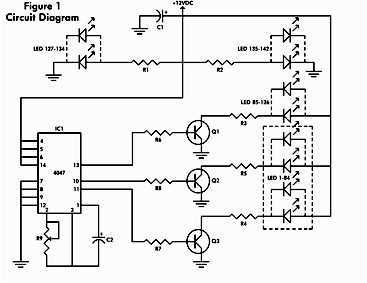
It consists of a 4047 low-power monostable/astable multivibrator, IC1, used in the astable mode to provide the timing pulses to control the flash rate of the LEDs. To accomplish the astable mode, pins 4, 5, 6, and 14 are...
The MSF transmitter transmits time data bit-by-bit over 60 seconds each minute by modulating a 60 kHz carrier frequency. It employs a continuous wave (CW) signal. Two bits are sent every second through variations in the duration and number...
This stereo noise blanker or suppressor attenuates noise by 45 dB when the music signal is low or absent; it functions primarily as a noise limiter. The noise blanker sensitivity... This circuit serves as a stereo noise blanker or suppressor,...

12V Battery Charge Nominal Discharge (Low) Indicator Circuit. This circuit monitors car battery voltage and provides an indication of nominal supply voltage, as well as low or high voltage. The 12V Battery Charge Nominal Discharge Indicator Circuit is designed to...