
Battery Charge Nominal Discharge Indicator Circuit

The 12V Battery Charge Nominal Discharge Indicator Circuit is designed to continuously monitor the voltage levels of a car battery, ensuring that the user is informed of the battery's status. The circuit operates by comparing the battery voltage against predefined thresholds that indicate nominal, low, and high voltage conditions.
The circuit typically comprises several resistors, which form a voltage divider that scales the battery voltage to a lower level suitable for input to an analog comparator or a microcontroller. The resistor values listed in the parts list, such as R1 (11.5kΩ), R2 (1.5kΩ), R3 (1kΩ), R4 (1.5kΩ), R5 (1.5kΩ), and R6 (10kΩ), are carefully selected to ensure accurate voltage readings.
When the battery voltage is within the nominal range, an LED indicator can be activated to signal that the battery is functioning properly. If the voltage drops below a certain threshold, indicating that the battery is low, a different LED may light up, alerting the user to the need for charging. Conversely, if the voltage rises above the nominal range, another indicator may activate to warn of potential overcharging conditions.
The circuit can be powered directly from the battery, ensuring it is always operational when the vehicle is in use. Additionally, a zener diode may be incorporated to protect the circuit from voltage spikes, which can occur during engine start-up or due to other electrical loads.
This battery monitoring system is crucial for maintaining battery health and longevity, as it enables timely interventions to prevent damage due to under-voltage or over-voltage conditions. Proper implementation of this circuit can enhance the reliability of automotive electrical systems.12V Battery Charge Nominal Discharge (Low) Indicator Circuit This circuit monitors car battery voltage. It provides an indication of nominal supply voltage as well as low or high voltage. PARTS LISTR11.5k?R21.5k?R31k?R41.5k?R51.5k?R610.. 🔗 External reference
Related Circuits
VCR Camera Video Detector Switch Controller Circuit. This video detector switch controller circuit utilizes the video output from a VCR or camera to... This circuit functions as a video detector switch controller, designed to manage the video output from a...
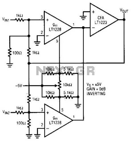
This unit captures the ATV signal by sampling the transmission line with minimal insertion loss. It features two N connectors for input and output connections, and a BNC connector is utilized for the video output. The detected output is...
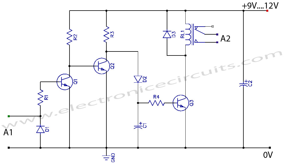
The circuit serves an educational purpose, necessitating simplicity. The construction will utilize only components that are already available, including a variety of resistors, capacitors, transistors, and no integrated circuits (ICs). The circuit is designed to demonstrate fundamental electronic principles through...
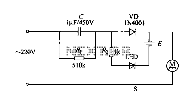
The electric shaver circuit is illustrated in Figure 1-17. It features a buck capacitor (C) rated at 1 µF and 450V, which connects through diode VD to charge 1.2V nickel-cadmium batteries. Additionally, after the buck converter, there is a...
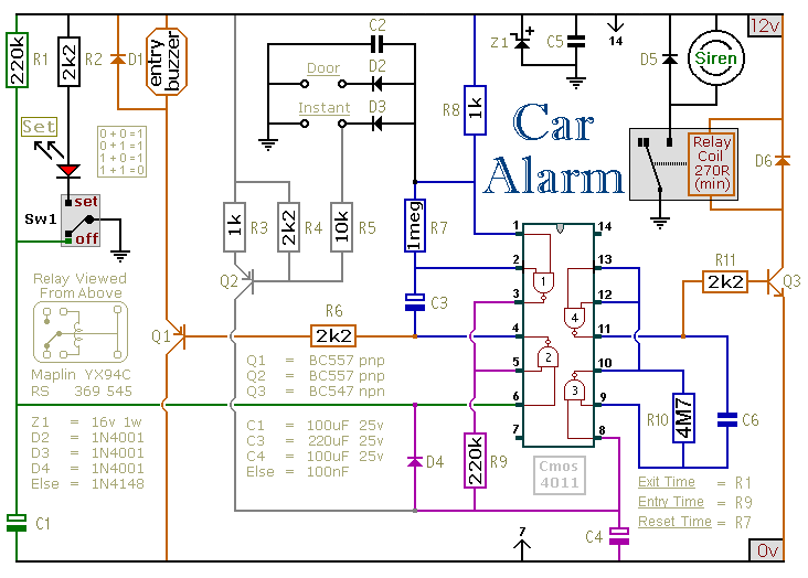
This circuit is designed to secure a vehicle at a low cost if constructed independently, making it more affordable than purchasing a commercial car alarm system. The alarm is activated by opening switch Sw1, which can be any small...
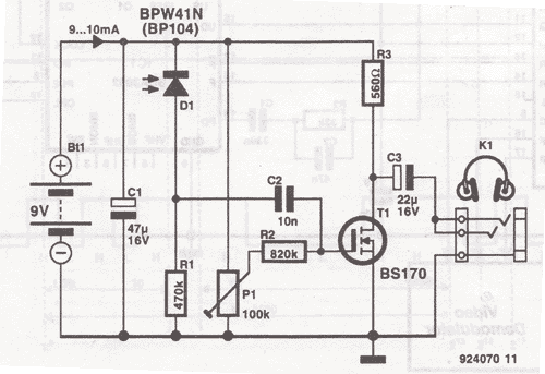
This wireless headphones transmitter ensures quality reception over a distance of 2 meters. The oscillator frequency ranges from 1750 kHz to 3500 kHz, and for the antenna, it... The wireless headphones transmitter operates within a frequency range of 1750 kHz...