
Battery charger circuit Schematic Diagram

The charger circuit is designed to efficiently charge a battery pack consisting of six cells, each rated at 2.4 volts. The total charging voltage of 14.4 volts is derived from the multiplication of the individual cell voltage by the number of cells in series. The pulsing mechanism operates at a frequency of 120 Hz, which facilitates effective energy transfer to the battery, ensuring optimal charging performance while minimizing heat generation.
The circuit typically includes a power supply unit that converts the AC mains voltage to a suitable DC voltage, which is then regulated to provide a stable output of 14.4 volts. This regulation is crucial to prevent overcharging, which can lead to battery damage or reduced lifespan.
A control circuit, often utilizing a microcontroller or dedicated charging IC, manages the pulse width modulation (PWM) signals sent to the battery. This modulation allows for precise control over the charging current and voltage, adapting to the battery's state of charge. Additionally, safety features such as overcurrent protection, thermal shutdown, and reverse polarity protection may be integrated to enhance reliability and safety during operation.
The output stage of the charger may consist of a switching regulator or a linear regulator, depending on the design requirements, efficiency considerations, and cost constraints. Capacitors and inductors are typically employed in the output stage to filter the voltage and current, smoothing out any ripples that may arise from the pulsing action.
Overall, this battery charger circuit represents a well-engineered solution for charging multi-cell battery packs, adhering to manufacturer specifications while incorporating modern electronic design principles to ensure safety, efficiency, and performance.This cahrger based on chargeing voltage 2, 4 Volts per cell, in accordance with most manufacterers recomendation. This circuit pulses the battery under with 14. 4 Volts ( 6 cells x 2, 4 volts per cell) at a rate 120 Hz. You are reading the Circuits of Battery charger circuit And this circuit permalink url it is 🔗 External reference
Related Circuits
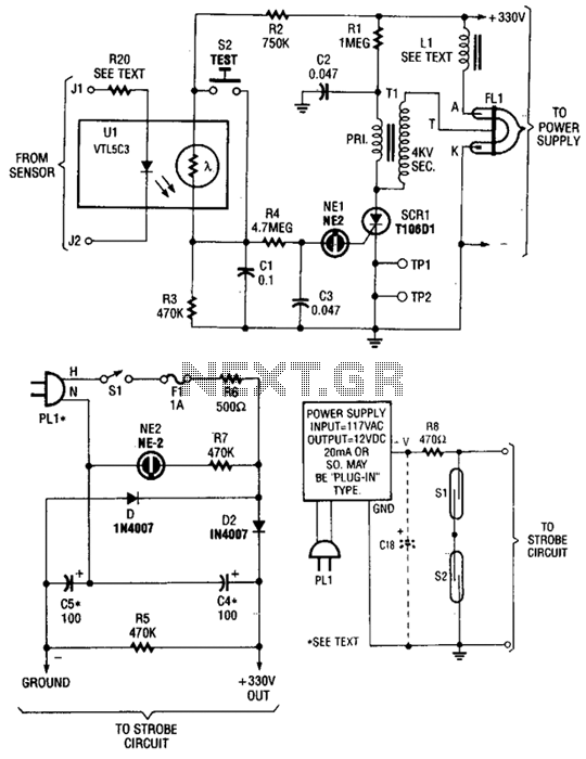
The circuit is activated by an LED/photoresistor isolator (U1), which combines a light-dependent resistor (LDR) and an LED in a single package. This device was selected for its high isolation characteristic of 2000 V, which is essential since the...
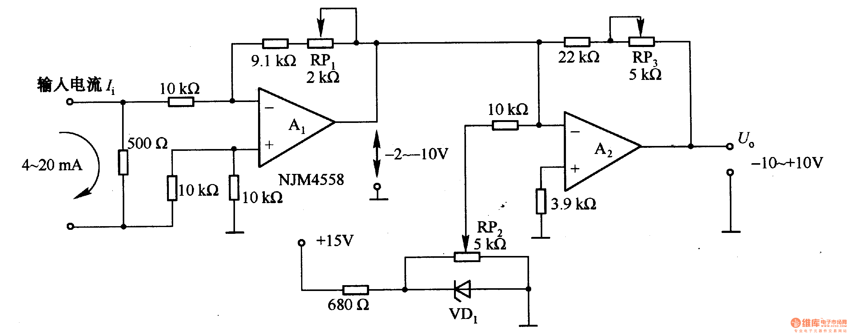
Figure 1-42 (a) is a voltage/current conversion circuit that converts a 0-10V input voltage into a 4-20mA output current. Adjusting resistor RP2 can set the input voltage (Ui) to 0V, resulting in an output current (I) of 20mA; similarly,...

This 555 timer circuit temperature monitoring system project can monitor temperature at up to four points. The system allows for the selection of whether the alarm should be triggered when the temperature increases or decreases, depending on the resistance...
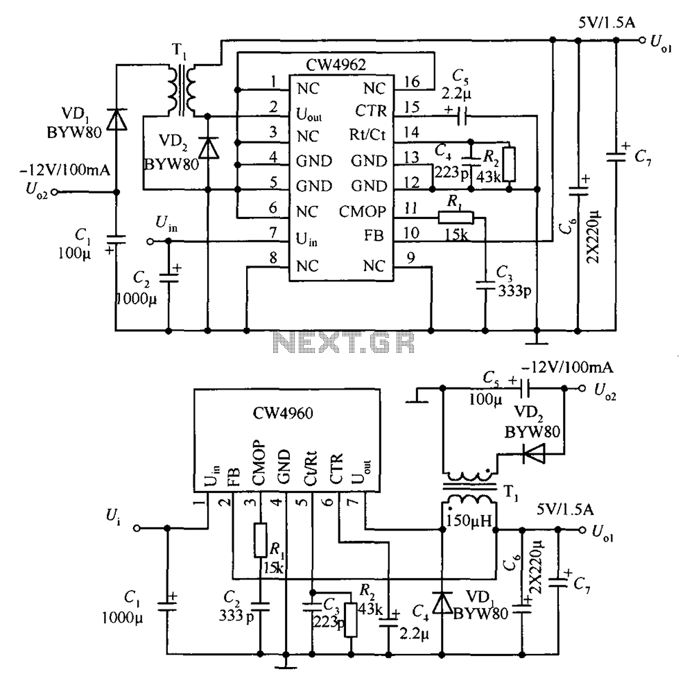
The circuit described is a stabilized power supply utilizing the CW4962 and CW4960 components, providing +5V at 1.5A and -12V at 100mA. The +5V output serves as the main power supply. The output circuit employs a transformer rather than...
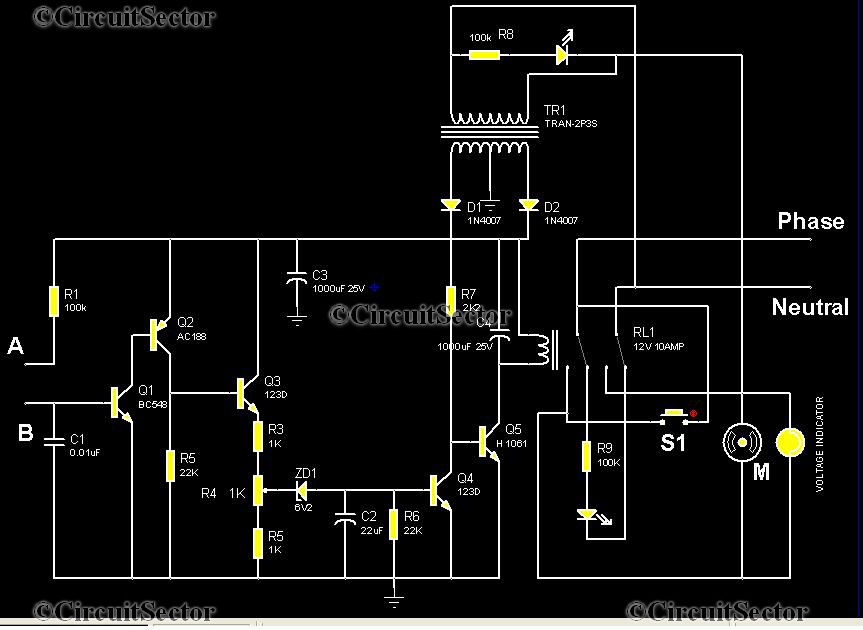
This is an automatic water tank controller designed to manage the operation of a water pump using a 12V 10A relay. When the water level in the tank creates a short circuit between points A and B in the...
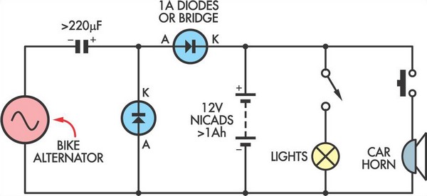
This simple circuit enables a 12V battery pack to be charged using a bike generator. The generator has a power rating of 3W, and this voltage multiplier circuit is designed to enhance the output voltage. The circuit employs a voltage...