
simple sound to light converter schematic

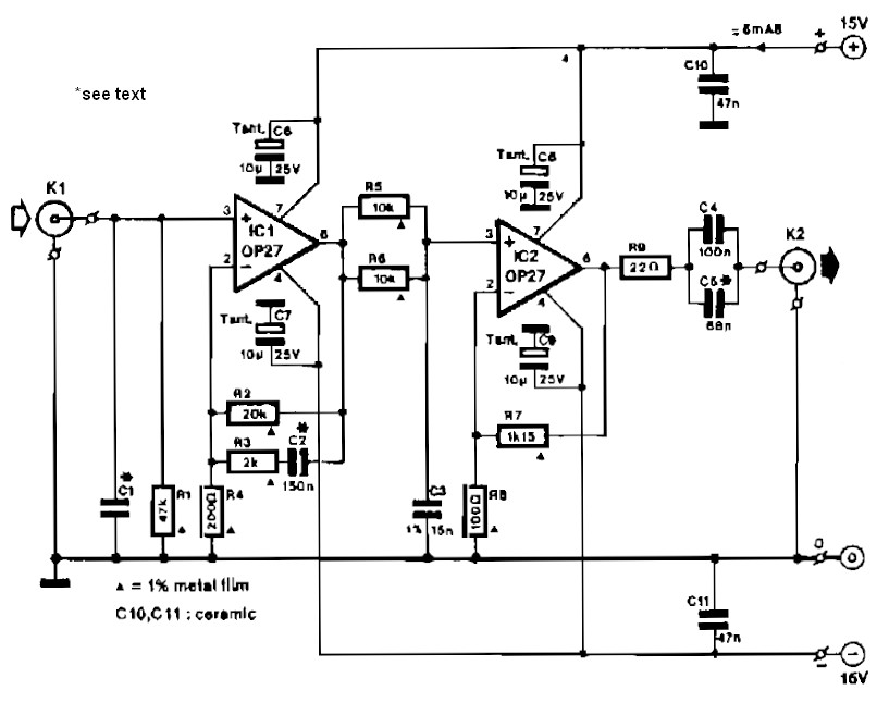
The described circuit serves as an audio signal visualizer, where the audio input is processed through a series of filters that segregate different frequency ranges. The buffer/amplifier stage ensures that the input signal is adequately amplified and buffered to prevent loading effects that could distort the signal. Capacitor C1 acts as a coupling capacitor, allowing AC signals to pass while blocking any DC component, thereby preserving the integrity of the audio signal.
The three filter circuits are designed to isolate specific frequency bands: the low-pass filter allows frequencies below a certain cutoff to pass, the mid-pass filter permits a range of frequencies around a designated center frequency, and the high-pass filter enables frequencies above a certain threshold to pass. Each filter's output is connected to a light-emitting diode (LED) that visually represents the presence of audio energy within its designated frequency range. The choice of resistor values RF and RV1 is critical, as they define the gain of the buffer and the overall response of the filters.
When audio input is received, the circuit responds dynamically; as the amplitude of different frequency components varies, the corresponding LEDs illuminate or extinguish, providing a visual representation of the audio spectrum. This functionality makes the circuit useful for audio analysis, music visualizations, or as a decorative element in audio equipment. The design can be further enhanced by adjusting the filter characteristics or adding more frequency bands for a more detailed visual output.A simple ambit for converting an audio arresting (such as one that comes from the apostle terminals of a CD player). The ambit basically consists of a buffer/amplifier date and three clarify circuits: a high-pass filter, a mid-pass filter, and a low-pass filter.
The achievement of anniversary clarify ambit drives a light-emitting di ode of altered color. The ascribe arresting is fed to the absorber date through C1. The ethics of RF and RV1 should be called so that the absorber is able to drive the three filters absorbed to its output. The low-frequency, mid-frequency, and high-frequency apparatus of the ascribe arresting are alone accustomed to canyon through the low-pass clarify (bottom filter), the mid-pass clarify (middle filter), and the high-pass clarify (topmost filter), respectively, appropriately amid them from anniversary other.
Changes in the achievement of a clarify account its agnate achievement LED to about-face on and off. In effect, agriculture a connected audio arresting to the ascribe of this ambit causes the LED`s to dance`. 🔗 External reference
Related Circuits
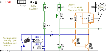
The schematic illustrates a Simple Motorcycle Alarm Circuit Diagram created by Ron J. It incorporates micro-switches to safeguard removable panels and... The Simple Motorcycle Alarm Circuit Diagram is designed to enhance the security of motorcycles by utilizing a series of...
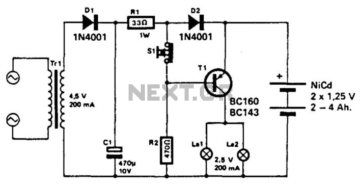
This unit utilizes a NiCad battery to supply power to an emergency lighting system. During a power failure, transistor T1 becomes forward biased, activating lamps L1 and L2. The batteries are typically maintained in a charged state. When the...
This circuit automatically controls the headlight of a motorcycle, turning it on and off independently of the light and ignition switches, as long as the battery is fully charged. The initial stage employs a 220-ohm resistor and ZD1 to...
Integrated-circuit U1-an LF351 or 741 op amp-is used as a comparator to control the light. Resistors R2 and R3 provide a reference voltage of about 2.5 volts at pin 3 of U1. When daylight falls on light-dependent resistor LDR1,...
This circuit diagram represents a simple yet effective transmitter circuit, capable of transmitting telephone conversations. When the telephone receiver is on the hook, the line voltage is approximately 48 volts. The R7 preset resistor is adjusted to achieve a...
Circuit IC1 provides a gain amplification of 40 dB, which decreases to approximately 20 dB when the frequency exceeds 500 Hz. To reduce resistor noise and the load on the operational amplifier at higher frequencies, the value of resistor...