
simplest 50mhz frequency counter

The PIC microcontroller serves as the core component in a variety of electronic circuits due to its versatility and ease of use. To successfully implement this microcontroller in a circuit, it is essential to first program it with the desired firmware. This process involves writing the code that dictates the microcontroller's behavior, which is typically accomplished using a specialized programming tool.
The Multi-PIC Programmer is one such device that facilitates the programming of various PIC microcontrollers. This programmer connects to a computer and allows users to upload their code to the microcontroller via a suitable interface, often utilizing a serial or USB connection. The programming process includes selecting the appropriate microcontroller model, loading the compiled code, and initiating the programming sequence through software that supports the specific programmer.
Before programming, it is crucial to ensure that the microcontroller is correctly powered and connected to the programmer as per the manufacturer's specifications. The circuit design may include additional components such as resistors, capacitors, and oscillators to ensure stable operation during the programming phase.
Once the programming is complete, the microcontroller can be integrated into the circuit, where it will control various functions as dictated by the programmed code. Proper testing and validation of the programmed firmware are essential to ensure that the microcontroller operates as intended within the overall circuit design.You will need to program the PIC micro-controller before you can use it in this circuit, for which you will need a programmer. You can find it by googling Multi-PIC Programmer . 🔗 External reference
Related Circuits
%2Bdecoder%2BCircuit%2Bschematic%2Busing%2BM8870.png)
This DTMF (Dual Tone Multi Frequency) decoder circuit identifies the dial tone from the telephone line and decodes the key pressed on the remote telephone. For the detection of DTMF signaling, the IC MT8870DE, a touch tone decoder IC,...
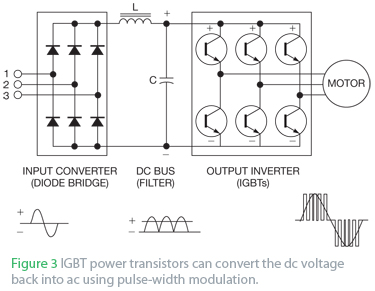
An AC drive controls AC induction motors and, similar to its DC counterparts, regulates speed, torque, and horsepower. A DC drive typically manages a shunt-wound DC motor, which features separate armature and field circuits. This teardown of the Schneider...
The circuit was designed to create a frequency generator that consists of seven steps during operation. It includes a crystal oscillator, which is an electronic circuit made of... The frequency generator circuit operates through a series of seven distinct steps,...

In the previous article about the Atmel AVR, only LED blinking was demonstrated without any external event influence on the microprocessor. All ports operated solely as outputs, with no input functionality. This article will illustrate how to connect control...
This calculator computes the resistor and capacitor values for a NE555 timer chip configured as an astable multivibrator (oscillator) or square wave generator. By entering the desired duty cycle and frequency, the calculator provides suitable values for the resistors...
Assistance is required for converting high frequency to low frequency and vice versa. A project involving a sensor is currently in progress, and the schematic is provided below. The conversion of high frequency signals to low frequency signals, as well...