
Simple Ultrasonic Wave Generator

The electronic circuit designed for generating ultrasonic sound waves typically utilizes an oscillator, which is responsible for producing a high-frequency signal. In this case, the frequency range specified is from 12 kHz and can extend to several hundred kHz, depending on the components used and the desired application.
The core of the circuit often includes a timer IC, such as the 555 timer, configured in astable mode to produce a continuous square wave output. This square wave is then fed into a transistor circuit that acts as a switch, amplifying the signal to drive an ultrasonic transducer. The transducer, often made of piezoelectric materials, converts the electrical signal into mechanical vibrations, producing ultrasonic sound waves.
Additional components may include resistors and capacitors to set the frequency of oscillation and stabilize the circuit's performance. Proper selection of these components is crucial to achieving the desired frequency and ensuring that the output signal is clean and free of distortion.
For applications such as pest control, ultrasonic cleaning, or distance measurement, the characteristics of the generated ultrasonic waves can be tailored by adjusting the circuit parameters. The circuit may also include a variable resistor or potentiometer to allow for fine-tuning of the frequency output.
In summary, this electronic circuit for generating ultrasonic sound waves is a straightforward design that leverages basic electronic components to produce high-frequency sound suitable for a variety of applications.Ultrasonic sound wave can be generated using electronic circuit. This simple electronic circuit can generate an ultrasonic wave with frequency range of 12 to . 🔗 External reference
Related Circuits
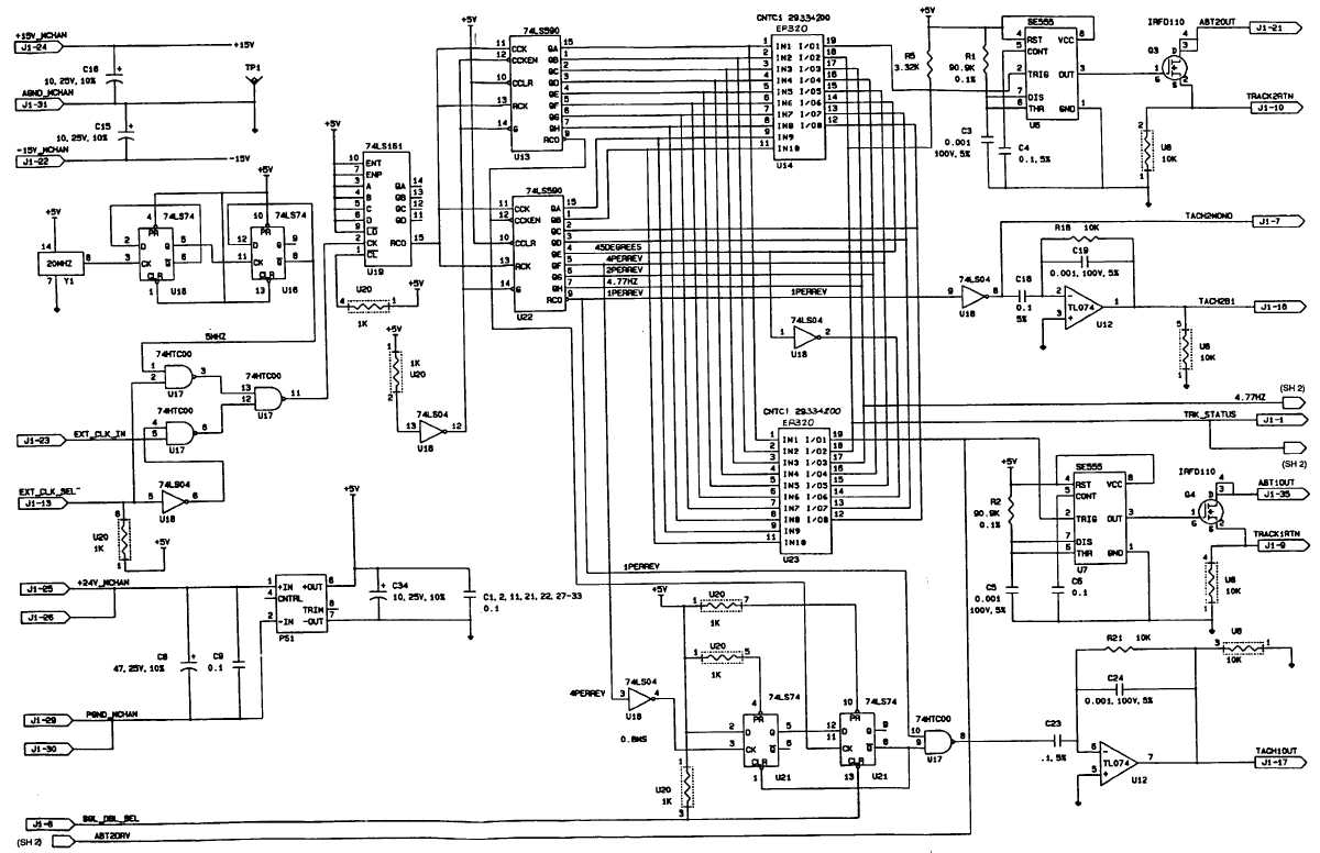
This circuit illustrates a Signal Generator Electronic Circuit Diagram. Features: Unless otherwise specified, resistance values are in ohms. The signal generator circuit is designed to produce various types of electrical signals, which can be sine, square, or triangular waves, depending...
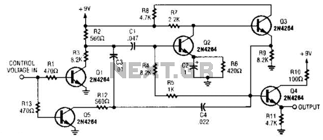
A DC control voltage varies the effective resistance in the feedback network consisting of capacitors C4, C3, C1 and resistors R12, R3. Additionally, Q2 and Q3 serve as the oscillator transistors. The circuit operates by utilizing a DC control voltage...
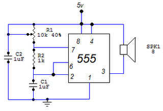
This circuit is based around the 555 timer circuit, used as an astable (free running) oscillator. The frequency (pitch) of the tone is set by the resistors and capacitors in the left side of the circuit. The first one...
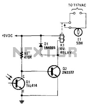
A phototransistor detects daylight. At dusk, it stops conducting, and Rl biases Q2, activating Kl, which turns on the light. At dawn, Ql begins to conduct, cutting off Q2. Kl deactivates, and the light turns off. The circuit utilizes a...
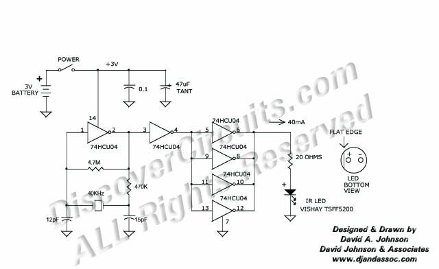
This 40 kHz crystal-controlled oscillator circuit drives an infrared LED with powerful 40 mA pulses. The circuit operates at a frequency of 40 kHz, determined by the crystal oscillator, which provides stable frequency output essential for applications requiring precise timing....
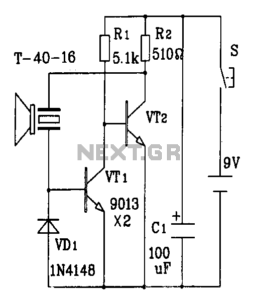
The discrete components ultrasonic transmitter circuit T/R-40-16 can emit a series of ultrasonic signals at a frequency of 40 kHz. This circuit operates at a voltage of 9V and has a current consumption of 25mA, with a control distance...