
Simple Stepper Motor ControllerCircuit Based On The 7404 IC

The simple stepper motor controller circuit utilizes the 7404 hex inverter IC to control the operation of a stepper motor. The 7404 IC consists of six independent inverters, which can be employed to generate the necessary control signals for the stepper motor. The circuit operates by providing a sequence of pulses to the motor windings, allowing for precise control of the motor's position and speed.
In this configuration, the input signals to the 7404 can be generated by a microcontroller or a simple switch mechanism. The output from the 7404 drives the transistors that act as switches for the motor coils. When a logic high signal is applied to an inverter input, the output goes low, and vice versa, creating a square wave pulse that energizes the motor coils in a specific sequence.
To ensure adequate heat dissipation, it is essential to incorporate heat sinks or other thermal management solutions, especially if the circuit operates at higher currents. The design may also include diodes across the motor coils to protect against back EMF generated when the motor is de-energized, thereby preventing damage to the circuit components.
Overall, this simple stepper motor controller circuit provides an effective method for controlling stepper motors with minimal components, leveraging the capabilities of the 7404 IC for reliable operation.The following circuit shows about Simple Stepper Motor Controller Circuit Diagram. This circuit Based On The 7404 IC. Features: suitable heat .. 🔗 External reference
Related Circuits
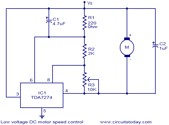
The circuit diagram illustrates a low voltage/low power DC motor speed controller utilizing the TDA 7274 integrated circuit from ST Microelectronics. The TDA 7274 is designed for low voltage and low power applications, featuring an internal voltage reference, a...
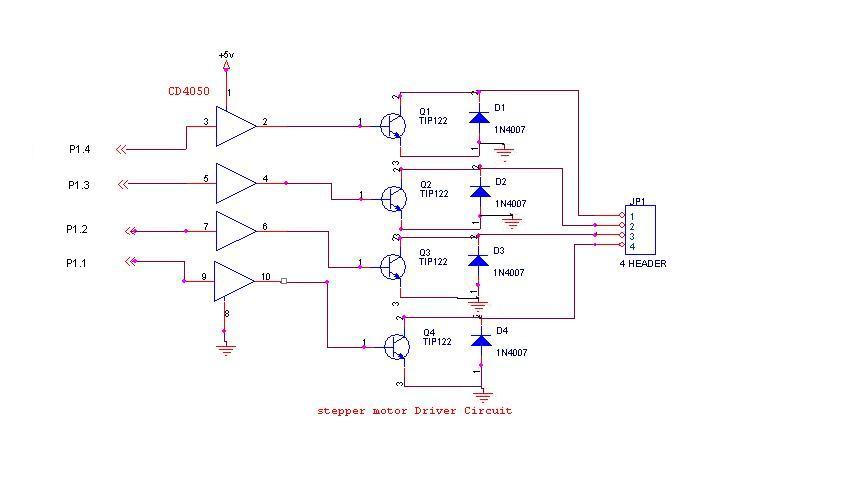
A 6V, 2A stepper motor is utilized in this circuit. The CD4050 hex buffer is employed to connect to the microcontroller. The output of the CD4050 is linked to the base of a TIP122 transistor. The emitter and collector...
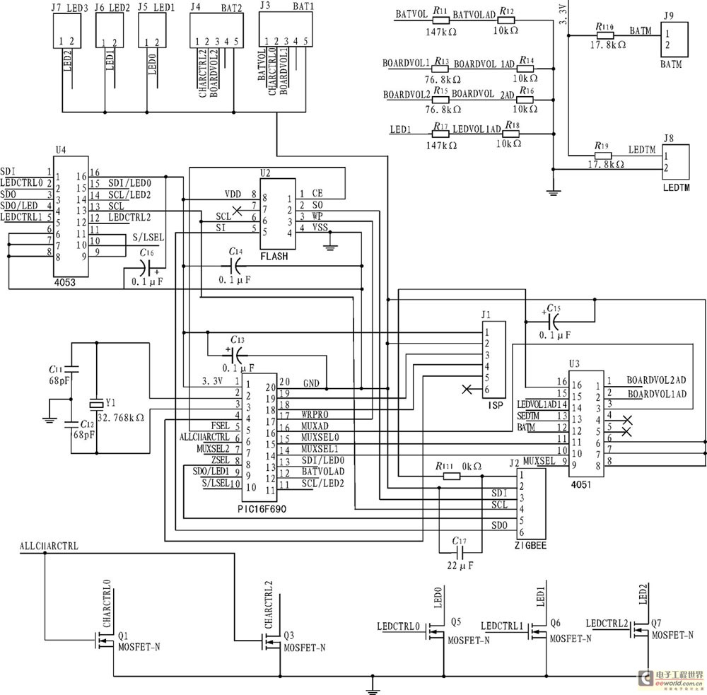
The development of a solar energy street lamp control device has progressed through three stages. The first generation featured a simple and crude function, allowing the light to be turned on or off, but required connection to a light-sensitive...
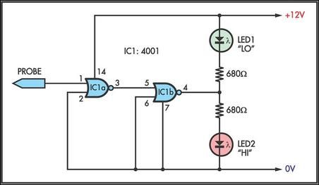
This simple logic probe has both LEDs illuminated with no signal at the input. However, due to the NOR gates connected to the probe, it indicates correctly when a high or low signal is present. It also functions correctly...
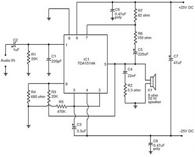
This document provides a circuit diagram of a car stereo. It includes a circuit diagram of a Class B 15 Watts audio amplifier designed using a dual op-amp and a transistor. The 15 W Class B audio amplifier circuit...
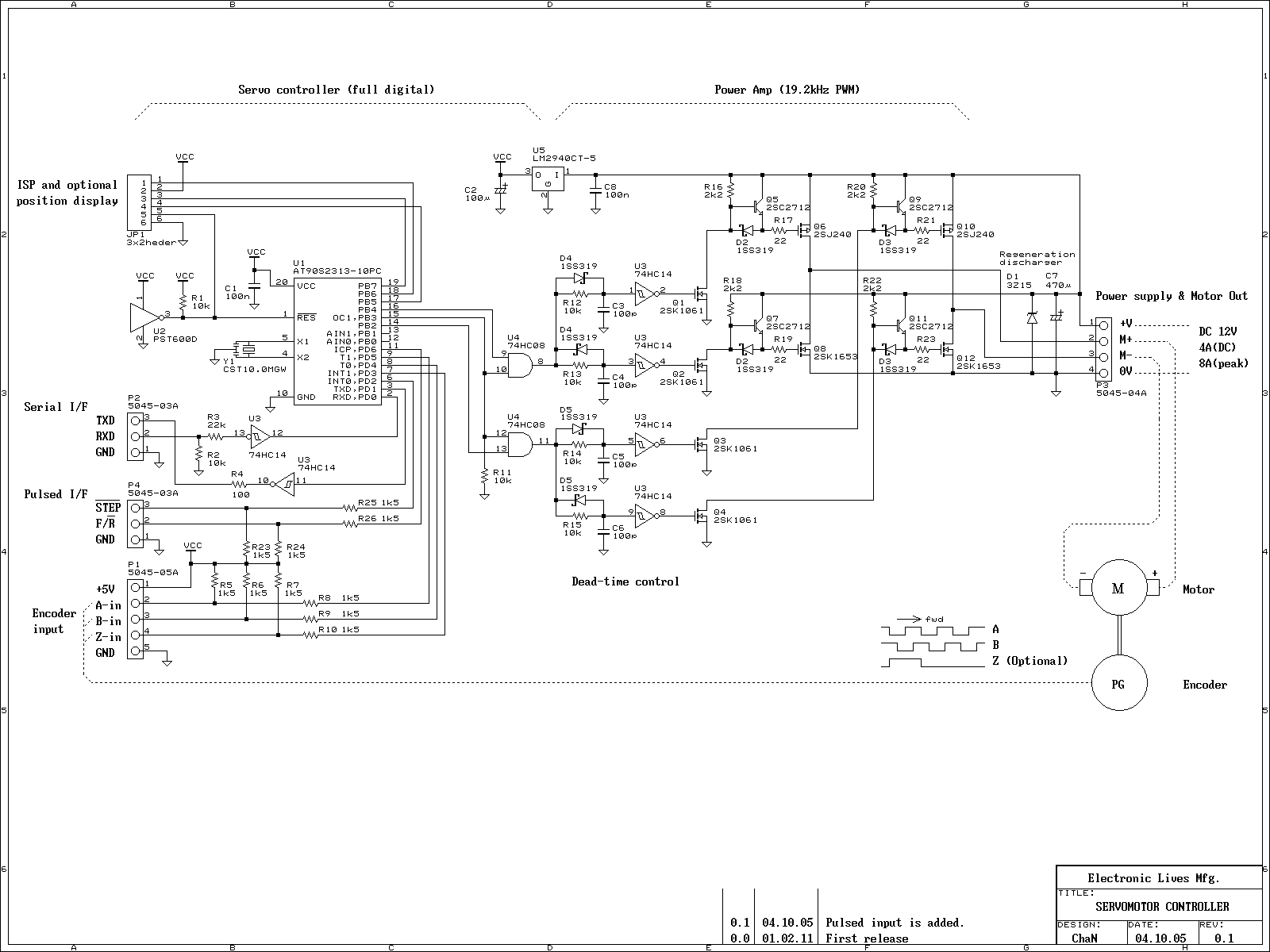
This is an experiment on the closed loop DC servomotor control system (SMC). It will be able to be used for practical use with/without some modifications. The closed loop servo mechanism requires real-time servo operations, such as position control,...